SATEL-EASy+
User guide
Version 1.33
22
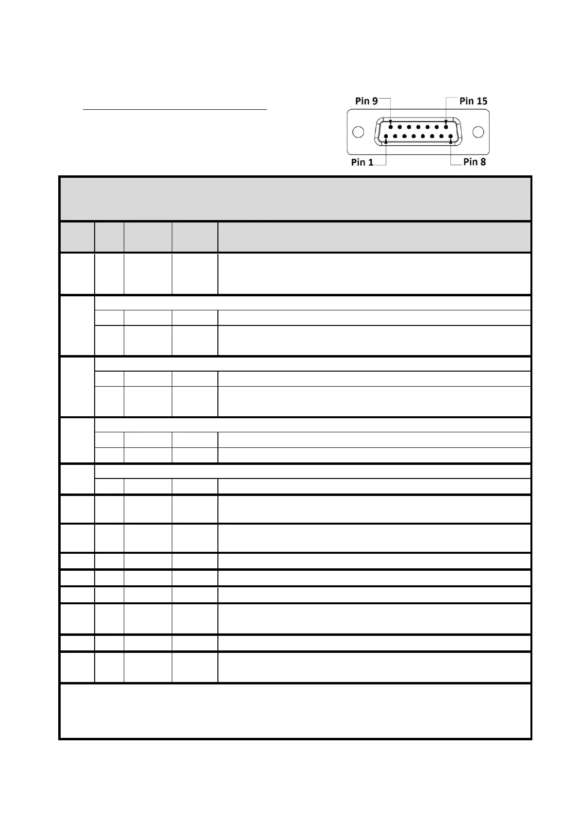
4.5 D15 connector SATEL-EASy+
SATEL-EASy+ radio modems: 15-PIN FEMALE D CONNECTOR PINOUT
I/O column below denotes the direction of the signal: "IN" is from DTE (Data Terminal Equipment) to the
radio modem. "OUT" is from the radio modem to DTE.
Data Terminal Ready. This pin can be used to wake-up the radio
modem from standby mode. >+3 VDC or not connected = ON,
<+0.6 VDC = STANDBY. By default, this pin can be left unconnected.
Pin 2 has alternative functions depending on the Port2 configuration, see below.
Carrier Detect (if Port2 Interface mode is RS-232)
Port2 Receive Data positive (if Port2 Interface mode is RS-422)
Shared input/output Data in RS-485 mode
Pin 3 has alternative functions depending on the Port2 configuration, see below.
Port2 Receive Data (if Port2 Interface mode is RS-232)
Port2 Receive Data negative (if Port2 Interface mode is RS-422)
Shared input/output Data in RS-485 mode
Pin 4 has alternative functions depending on the configuration, see below.
Port2 Transmit Data (if Port2 Interface mode is RS-232)
Port2 Transmit Data positive (if Port2 Interface mode is RS-422)
Pin 5 has alternative functions depending on the hardware assembly, see below.
Port2 Transmit data negative
Clear To Send. This signal indicates that the radio modem serial
interface is ready to receive data from DTE. Note*)
Operating voltage ground / signal ground.
Signal ground has a galvanic connection to the modem casing.
Port1 Receive Data to DTE from the radio modem
Data Set Ready. Indicates that the radio modem is ON.
Port1 Transmit Data from DTE to the radio modem.
<2VDC or connected to ground = Programming Mode
>3VDC or not connected = Data Transfer Mode Note**)
Request To Send from DTE. Note*)
Operating Voltage +7...+27.5 VDC
Note! Unused pins can be left unconnected.
Note*) RTS and CTS signals apply to the selected Data port only (Port1 or Port2).
Note**) Programming Mode is for bringing the modem to a serial port state: Data port 1 38400N81. By
default, modem is Data Transfer Mode in a case Pin 12 is floating.