SATEL-EASy+
User guide
Version 1.33
24
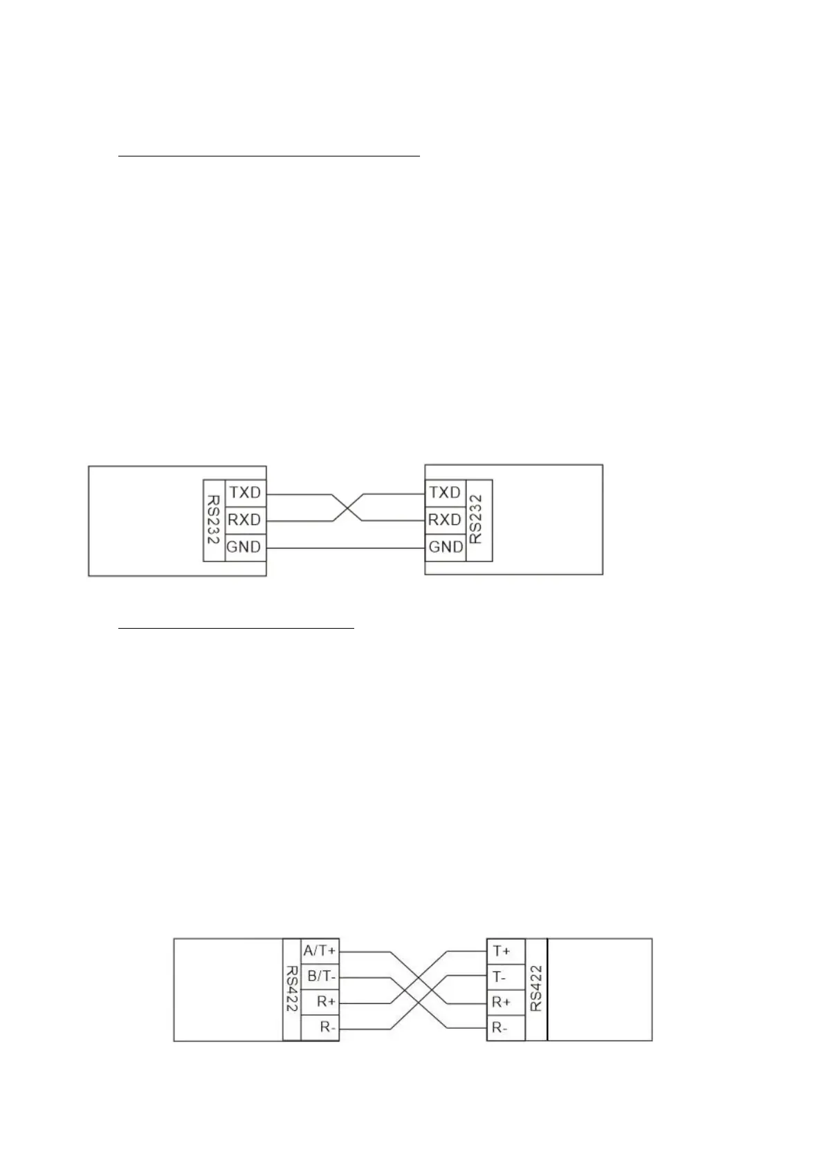
5.1 RS-232 interface (Port 1, Port 2)
RS-232 standard defines the method of transferring binary single-ended data serially between
DTE and DCE. Although the standard defines the electrical characteristics, timing and meaning
of the signals, as well as the pin out of connectors, it is applied in a multitude of slightly differing
ways (e.g., different pin configurations). For this reason, different computers and peripherals are
not necessarily directly compatible with each other.
RS-232 standard defines transmission lines, in which each single signal line level is referenced to
a common ground level. When connecting equipment using RS-232 interface make sure that the
equipment is connected sharing the same ground potential. Major differences in ground
potentials may result to large current flow in the ground (GND) wire and may lead to a
malfunction or damage the connected devices!
RS-232 has been designed for serial data transfer over short distances (usually less than 15 m).
For longer distances, RS-422 or RS-485 is better suited in order to maintain the integrity of data.
5.2 RS-422 interface (Port 2)
RS-422 standard defines a serial data transfer method, which is similar to the RS-232 standard.
In RS-422 however, the signal lines are differential transmission lines. Differential transmission
line is formed by using two signal wires together which are in opposite polarity to each other.
Because the state of the signal is defined by the mutual voltage difference (hence the name
differential), any common mode disturbances induced into the lines will cancel out.
Transmission distance can be considerably longer than when using RS-232 type of connection,
and distances of 1 km are possible.
As an example, let’s examine the TX-signal: TX-signal will be transmitted using two lines (A and
B). A logic “1” corresponds to a situation where the voltage on line A is greater than the voltage
on line B. Correspondingly a logic ”0” corresponds to a situation, where the voltage on line A is
smaller than the voltage on line B.