SATEL INTEGRA Plus 7
function is indicated by the arrow on the left-hand side. How the function related information
is presented depends on the specific character of the given function.
The way of display backlighting is programmed by the installer.
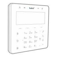
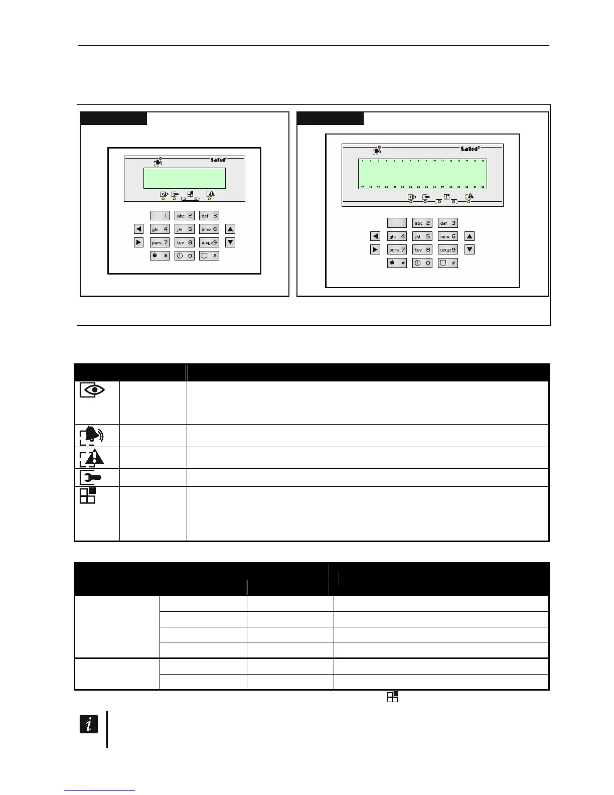
INT-KLCDS INT-KLCDL
Fig. 2. Keypads without flap.
5.1.2 LED indicators
LED Color Function description
green ON – all keypad operated partitions are armed
blinking – some keypad operated partitions are armed or exit delay
countdown is running
red ON or blinking – alarm or alarm memory
yellow blinking – trouble or trouble memory
green blinking – service mode is entered
green if zone status is being presented or the keypad is switched to graphic
programming mode (see: “Selection from the multiple-ch
oice list”
p. 15), two LEDs indicate which data set is being dis
played (see:
table 2)
Table 1. Description of keypad LEDs.
LED
Data type
left side/upper right side/lower
Information
OFF OFF numbers 1-32
OFF ON numbers 33-64
ON OFF numbers 65-96
Zones/Outputs
ON ON numbers 97-128 / 97-256
OFF
OFF system addresses 0-31 (00-1F HEX)
Expanders
OFF
ON system addresses 32-63 (20-3F HEX)
Table 2. Information presented by the
LEDs
.
Information about the armed state can be extinguished after a time period defined by
the installer.