5.4 Digital functions
Thedigitalfunctionsutilizedvariesdependingonsystemconguration,upto20digitalfunctions
can be implemented thru left- and/or right switch panels with programmable assignments to up
to 14 digital outputs.
In excess the On-button may also be assigned a digital output.
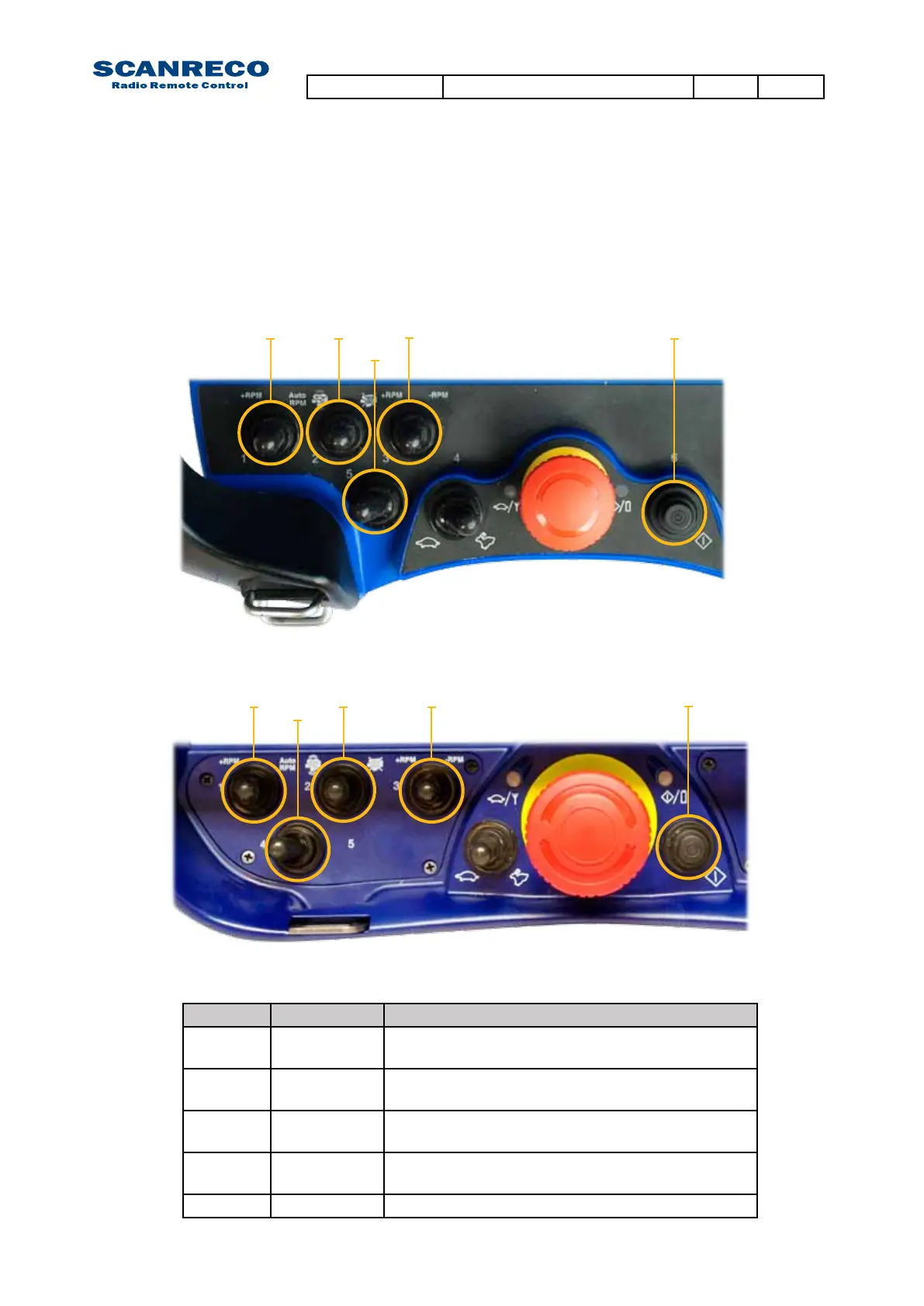
Below shows PCU platforms standard digital inputs and default Central Unit output assignment
Position Type Central Unit
301 3 way detent
toggle
Digital output 1 / Digital output 1 Parallel with ana-
logue input movement (AutoRPM engine feature)
302 3 way spring
back toggle
Digital output 2 / Digital output 3 (Engine start /
Engine stop)
303 3 way spring
back toggle
Digital output 4 / Digital output 5 (Engine RPM+ /
Engine RPM-)
304/305 2 way detent
toggle
Digital output 6 (Optional)
On-button Push button Digital output 7
301
301
304
305
302
302
303
303
On-button
On-button
PCU MINI Standard assignment
PCU MAXI Standard assignment
Document type Document number PageRev
Service Manual S071 C
18 of 46
 Loading...


