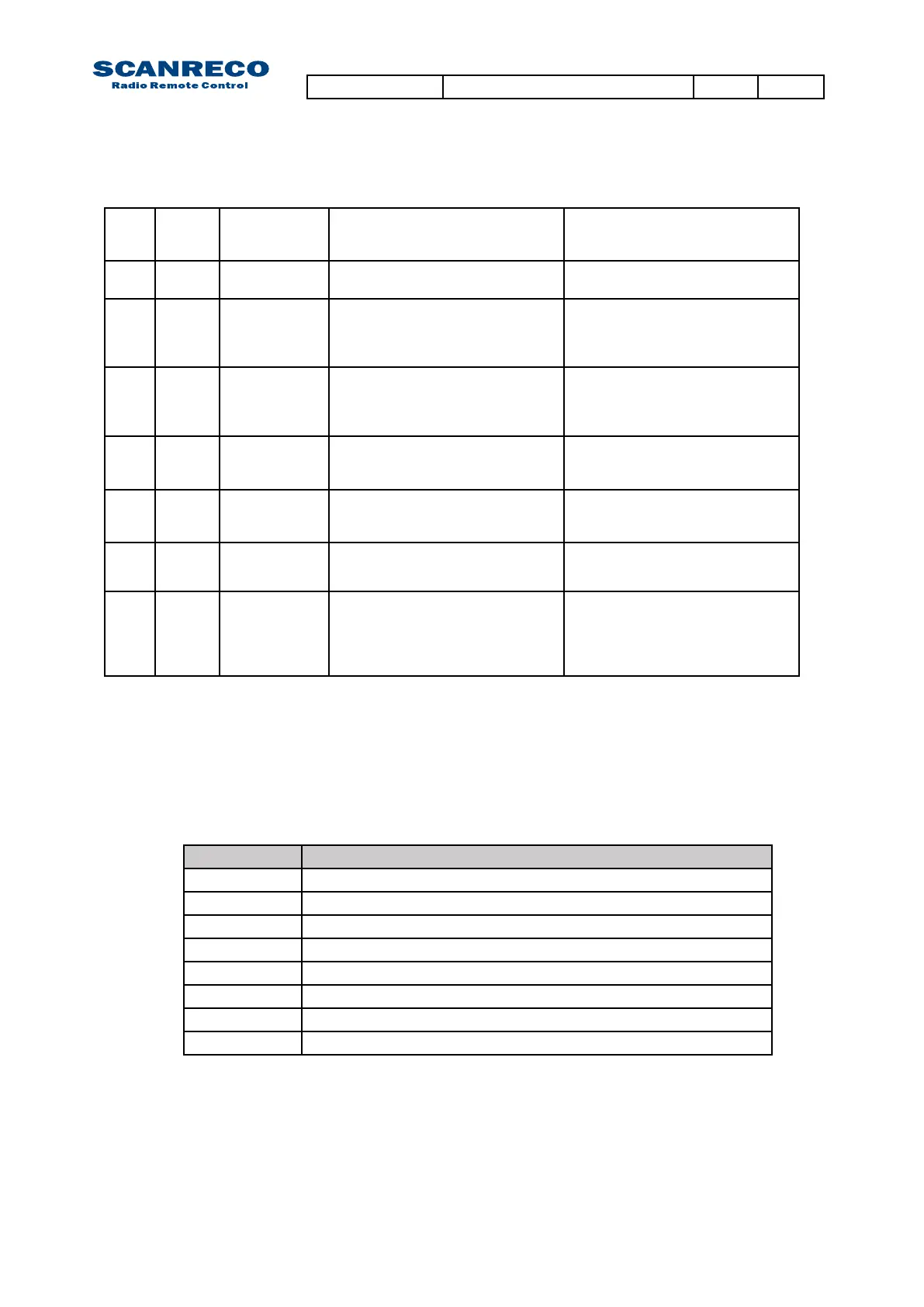
14. 01 ID programming
failure
ID-code and/or parameter settings
not accepted.
System will self reset.
Verify ID-programming procedure.
Reset application program.
14. 02 Program
failure
Programmable logic parameter error System will self reset.
Reset application program.
15. x PWM output
failure
Analogue output short circuited or
overloaded.
(3rd sequence declares related
output;1A,1B….).
System will self reset.
Check analogue output connections.
Remove terminal connector and reset
system.
16. x PWM output
failure
Analogue output not connected
(Programmable feature).
(3rd sequence declares related
output;1A,1B….).
System will self reset.
Check analogue output connections.
Remove terminal connector and reset
system.
17. 01 Low supply
power
Lowpowersupply(Below8,5VDC) System will self reset.
Check power supply and supply
connections.
17. 02 High supply
power
Highpowersupply(Above36,0VDC) System will self reset.
Check power supply and supply
connections.
98. n/a UndenedPCU
error
UndenederrorinPCU. Diagnose PCU via TEST MODE
99. n/a UndenedCU
error
UndenederrorinCU. System will self reset.
Remove all terminal connectors
Check power supply and supply
connections.
Reset system.
7.2.1 Error codes (continued)
Indications Meaning
1 Analogue input 1 not at zero position during start-up
2 Analogue input 2 not at zero position during start-up
3 Analogue input 3 not at zero position during start-up
4 Analogue input 4 not at zero position during start-up
5 Analogue input 5 not at zero position during start-up
6 Analogue input 6 not at zero position during start-up
7 Analogue input 7 not at zero position during start-up
8 Analogue input 8 not at zero position during start-up
7.3 Portable Control Unit error codes
The Portable Control Unit monitors all analogue and digital inputs for faults and uses the Power-
LED and BUZZER to indicate alarms.
Below available error codes:
Document type Document number PageRev
Service Manual S071 C
29 of 46
 Loading...


