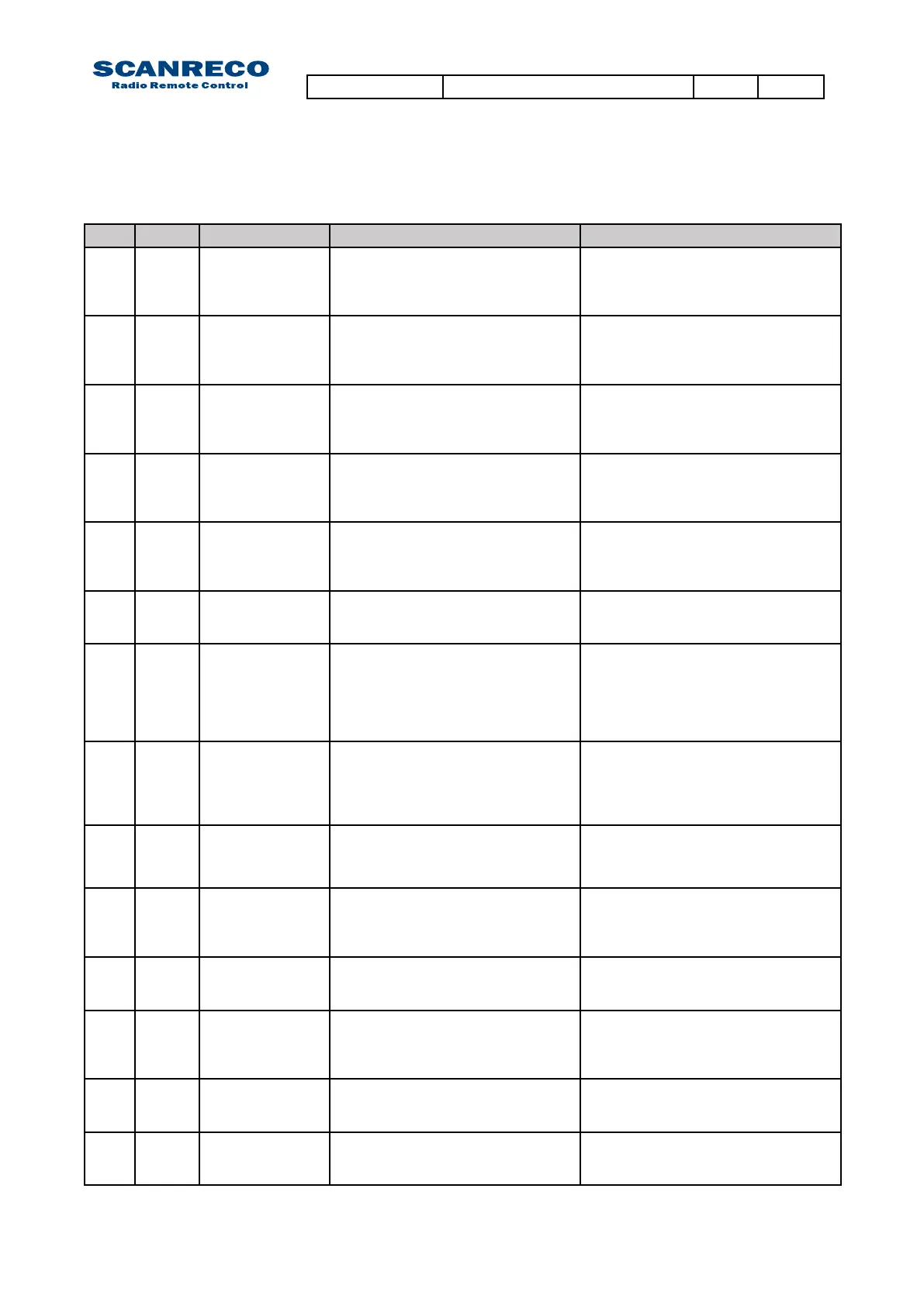
2nd 3rd Description 0utputs system
04. 00 Short circuit;
Digital output
Digital output (1-14) short circuited
or overloaded (Could be any of the
available 14 outputs)
System will self reset.
Check digital output connections.
Remove terminal connector and reset
system.
05. 00 Error input
triggered
(Danfoss CU
only).
Error signal for Danfoss valve
triggered (Could be any of the
available 8 inputs)
System will self reset.
Check analogue output connections.
Remove terminal connector and reset
system.
06. x Illegal voltage
analogue
output
Wrong voltage on analogue output
(3rd sequence declares related
output;1A,1B….).
System will self reset.
Check analogue output connections.
Remove terminal connector and reset
system.
07. x Illegal voltage
analogue
output
Wrong current on analogue output
(3rd sequence declares related
output;1A,1B….).
System will self reset.
Check connections.
Remove terminal connector and reset
system.
08. 01 CAN Passive CAN bus in passive mode. System will self reset.
Check CAN connections.
Check other nodes on bus and reset
system.
08. 02 CAN I/O
Buffer
overow
CAN overrun; either the CAN input or
CAN output buffer are full
System will self reset.
Resetsystem,re-initiateviaCAN
controller.
08. 03 CAN physical
layer error
Bad communication/transmission System will self reset.
Check CAN connections.
Check other nodes on bus and reset
system.
08. 04 CAN PDO
length
exceeded
PDO length is to long System will self reset.
Resetsystem,re-initiateviaCAN
controller.
08. 05 CAN PDO
length error
PDO length is too short System will self reset.
Resetsystem,re-initiateviaCAN
controller.
08. 06 CAN Transmit
COB-ID
collision
To many collisions on CANbus System will self reset.
Check CAN connections.
Check other nodes on bus and reset
system,re-initiateviaCANcontroller.
10. 00 PCU failure;
Emergency
stop
Error transmitted from PCU: Illegal
signal from PCU emergency stop
switch
System will self reset.
Check emergency stop switch on PCU
11. 00 PCU failure;
Analogue
input
Error transmitted from PCU:
Analogue input active on start-up
System will self reset.
Ensure all analogue inputs on PCU are
at zero/neutral position.
Restart PCU.
12 00 PCU failure;
Analogue input
Error transmitted from PCU: Signal
redundancy test; illegal signal from
analogue input.
System will self reset;
Diagnose PCU via TEST MODE
13. n/a PCU failure;
Analogue
input
Error transmitted from PCU: Signal
redundancy test; illegal signal from
analogue input.
System will self reset;
Diagnose PCU via TEST MODE
7.2.1 Error codes (continued)
Document type Document number PageRev
Service Manual S071 C
28 of 46
 Loading...


