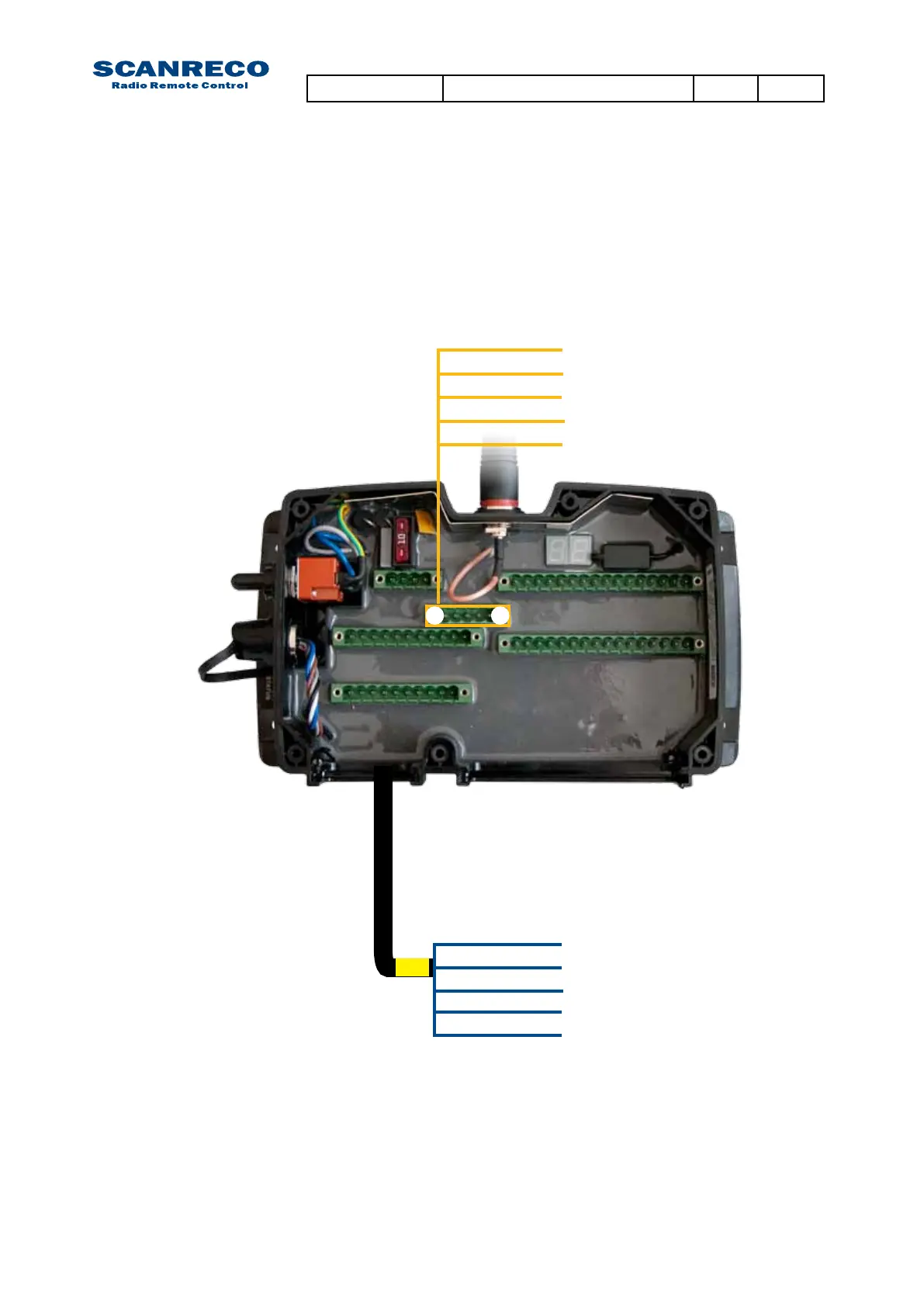
5.7 Terminal schematics for Central Unit G2B CAN interface
The Central Unit is equipped with terminal connections for CAN. The drawing below declares the access
points both from the inside terminals (above) and the standard cable kit (below).
NOTE:
*asvariouscablekitsexists,pleaserefertochapter13orsystemtechnicalspecicationforfur-
ther information
TheCentralUnitG2Bisnotequippedwithaspecic“STOPloop”connection,ifneededadigital
outputareinsuchcasesassigned;ifmoreinfoisrequired;refertosystemtechnicalspecication.
If required; a terminator resistor can be installed between points 4 & 5: the resistor value needs to
bedenedbythesysteminstaller.
5= CAN L
4= CAN H
3= GND
2= CAN L
1= CAN H
1 = CAN H
4 = CAN H
2 =
CAN L
5 =
CAN L
3 = GND
1
5
EX*
Document type Document number PageRev
Service Manual S071 C
21 of 46
 Loading...


