Seatex DPS 200 Installation Manual, rev. 4 Installation
7
3 INSTALLATION
This chapter covers installation of the DPS 200 unit and the GPS/GLONASS and the IALA
Beacon antennas. A separate installation manual [5] covers Seastar demodulator installation
and connection to the Inmarsat terminal onboard the vessel for reception of
DGPS/DGLONASS correction signals.
The installation includes:
1. Location of the system parts (the DPS 200 unit and the GPS/GLONASS antenna )
2. Mounting of the DPS 200 cabinet
3. Installation of the coax connectors
4. Mounting of the GPS/GLONASS antenna and cable
5. Connecting cables between DPS 200 and external equipment
6. System start
7. Editing setup file
3.1 System components
This chapter describes a typical ship installation of the DPS 200 system. A standard system
delivery consists of:
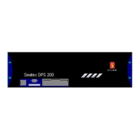
1. DPS 200 unit
2. Cabinet, 6U
3. Keyboard with rollerball
4. IALA Beacon receiver (included in the DPS 200 unit)
5. GPS/GLONASS antenna
6. DGPS Beacon antenna
7. DPS 200 User's Manual
8. DPS 200 Installation Manual
9. DPS 200 Site Manual
10. Interconnection cable
11. Mains cable
12. Antenna mounting rod
Options:
1. Coax cables for GPS/GLONASS and the IALA Beacon antennas
2. Coax connectors
DPS 200 is supplied in different configurations depending on application and specific user
needs. The DPS 200 cabinet contains the DPS 200 unit and the keyboard with rollerball.