Seatex DPS 200 Installation Manual, rev. 4 Installation
19
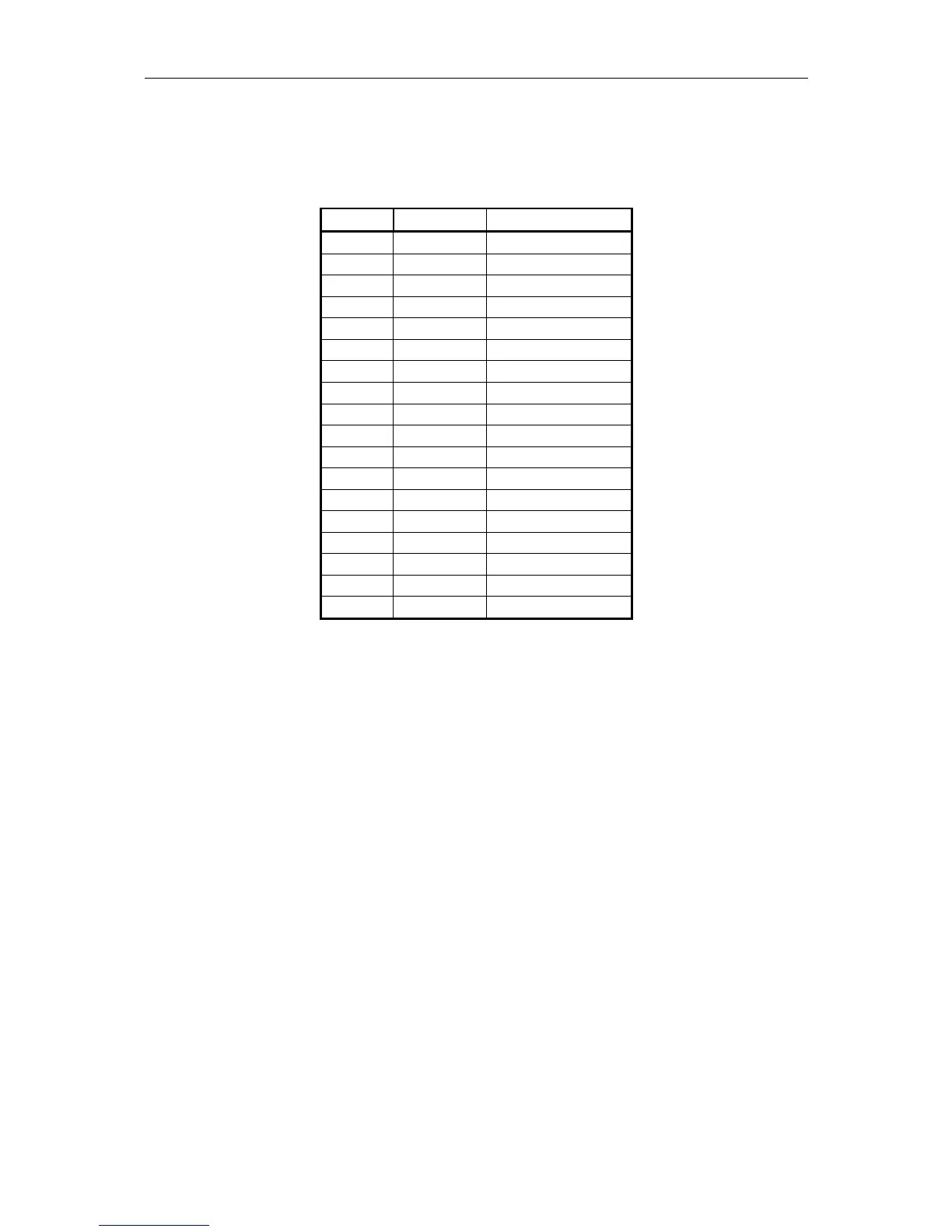
The Aux-Serial port makes it possible to increase the number of communication ports. On the
25-pin DSub female connector, six comports are available. The ports are default RS-232 serial
lines. The pin layout is described below.
Pin no. Signal Line
1 GND Com4
14 RX Com4
2 TX Com4
15 GND Com14
3 RX Com14
16 TX Com14
18 GND Com15
6 RX Com15
19 TX Com15
7 GND Com16
20 RX Com16
8 TX Com16
21 GND Com17
9 RX Com17
22 TX Com17
10 GND Com18
23 RX Com18
11 TX Com18
Table 5 Pin layout for Aux-Serial Port
3.7.3 PPS signal
A 1 pulse-per-second (1PPS) signal synchronised with GPS time is available from the BNC
plug at the rear of the DPS 200 unit. This PPS signal originates from the GPS receiver within
the unit. This PPS signal is buffered and fed to the BNC plug at 50 Ohm impedance. The high
level is at +5V and the low level is at 0V. The PPS signal is active high and has a nominal
pulse width at 9 ms. The 1 PPS is generated exactly once every second with its rising edge
synchronised to GPS time.
At the front of the DPS 200 unit there are four LED indicators. The indicator to the left
appears green when the system is turned ON. The indicator to the right is turned on and
appears green every time a PPS pulse is generated from the GPS/GLONASS receiver.