Seatex DPS 200 Installation Manual, rev. 4 Installation
16
3.7 External inputs and outputs
3.7.1 Connectors
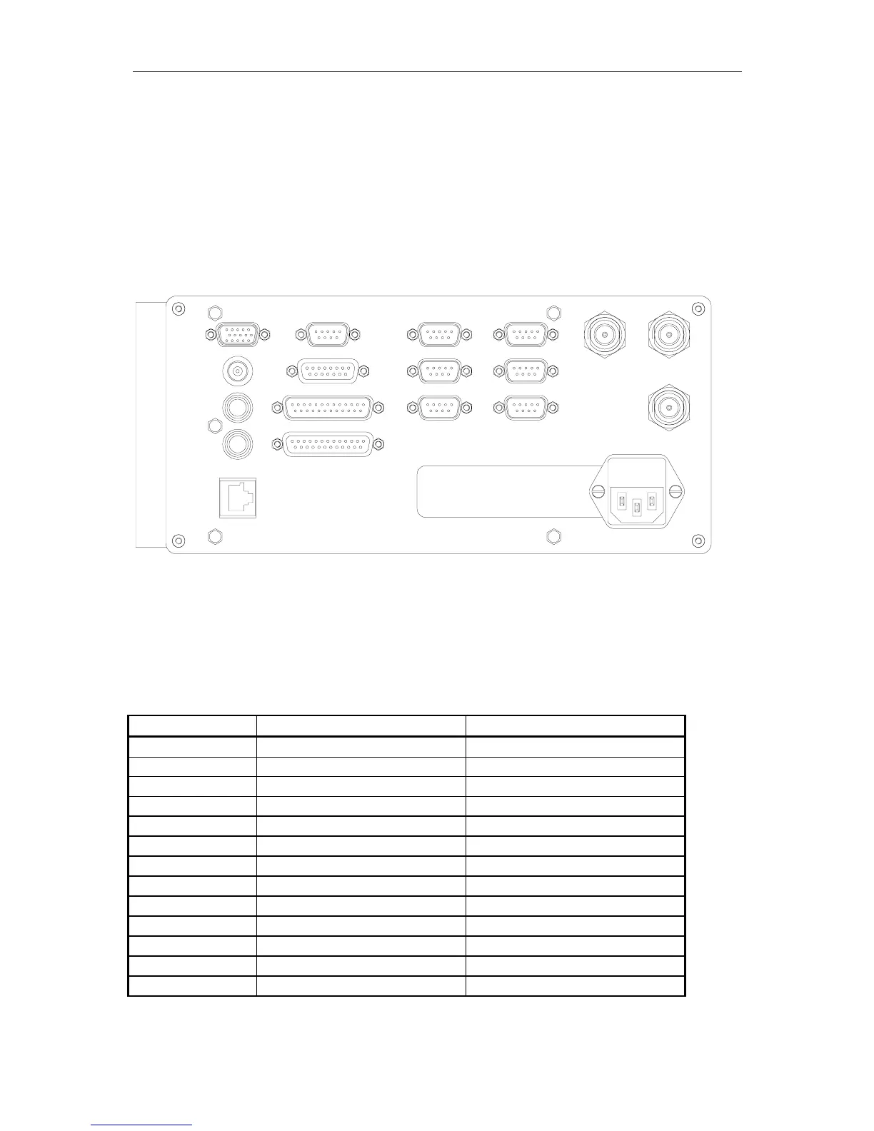
The rear panel of the DPS 200 unit contains communication interface ports for interfacing to
external systems. These ports are individually galvanically isolated.
Figure 1 Rear view of the DPS 200 unit
The use of the different connectors:
Connector Type Connected To
VGA Video display unit
PPS BNC-Connector Not in use
Mouse PS/2 Mouse
Keyboard PS/2 Keyboard
Net Ethernet output Not in use
Com2 - Com10 9 pin Dsub male User configurable
MRU (Com12) 15 pin Dsub female User configurable
LPT1 25 pin Dsub female Not in use
Aux-Serial 25 pin Dsub male Not in use (user configurable)
GPS Ant1 N-Connector 50 Ohm female GPS antenna
GPS Ant2 N-Connector 50 Ohm female Not in use
IALA Ant3 N-Connector 50 Ohm female IALA antenna
100-240 V AC Power Input of 110/220 V AC
Table 1 Connectors
Fuse : 2A
Input : 100-240VAC/47-63Hz/100VA
NET
KEYB
MOUSE
PPS
VGA
COM9
COM6
MRU
AUX - SERIAL
LPT1
grounded outlet only
Class1: Must be connected to
COM7
COM10
COM2
COM5
COM8
IALA
ANT3
GPS
ANT1
GPS
ANT2