Seatex DPS 200 Installation Manual, rev. 4 Installation
20
3.7.4 Connecting procedure
See drawing 36200-GD-006 on page 46 for an overview of the electrical installation.
1. Connect the GPS/GLONASS antenna cable to the connector marked Ant.1 on the rear of
the DPS 200 unit.
2. Connect the IALA Beacon antenna cable to the connector marked Ant.3 at the rear of the
DPS 200 unit.
3. Connect input and output connections including gyro data to Com5 through Com10.
4. Connect the VGA monitor cable, the mouse and keyboard cables to the rear of the DPS
200 unit.
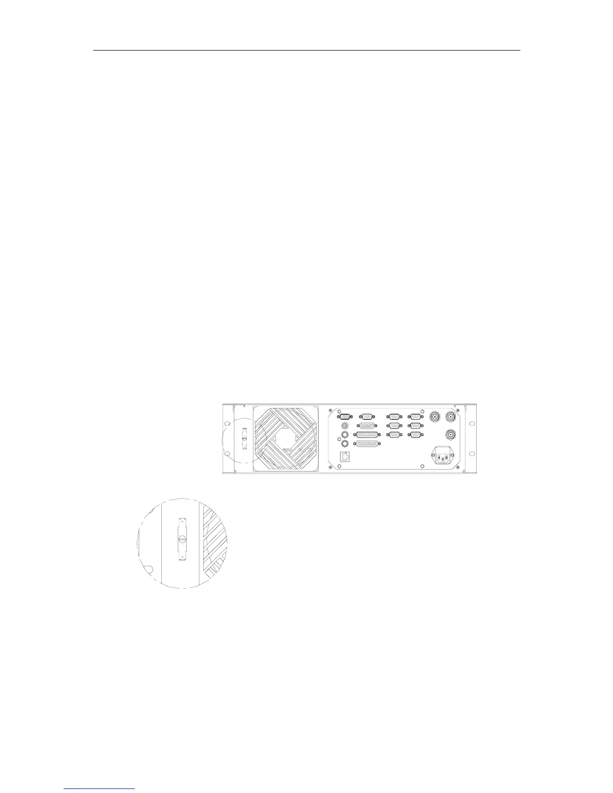
5. Connect a grounding cable from the grounding terminal at the rear of the DPS 200 unit, as
shown in Figure 2, to the grounding terminal inside the cabinet.
6. Connect a grounding cable from the grounding terminal inside the cabinet to a good
grounding point, e.g. to the ships structure.
7. Connect power to the connector at the rear of the DPS 200 unit.
A
DETAIL A
Figure 2 Grounding terminal detail