24
There are no jumpers or cables to set on this module, just wiring from the converter (wires are
fixed here) to the Main Fire Alarm Board.
Initiating circuits must be wired from the MR-2300-A module to the Main Fire Alarm board. For
example, Initiating circuit 1 positive (red) and negative (black) wires are connected to the
positive and negative terminals (respectively) of Initiating circuit 1 on the Main Fire Alarm
Board. From the MR-2300-A converter Initiating circuits are wired out to the devices from the
positive and negative terminals marked DET OUT and the circuit return wires are brought back
to the converter module to positive and negative terminals marked DET RET.
To convert all 12 initiating circuits of the Fire Alarm Panel, two of these MR-2300-A Input Class
A Converter Adder Modules are required.
6.3 MR-2300-NC4/MR-2300-NC2 Output Class A Converter Adder
Module
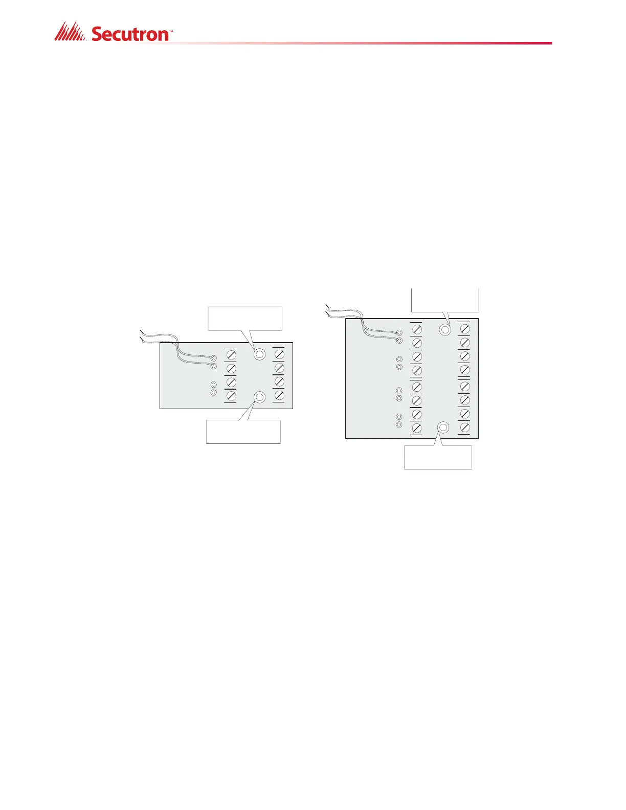
Figure 9 MR-2300-NC4/MR-2300-NC2 Output Class A Converter Adder Module
Indicating circuits must be wired from the MR-2300-NC4/MR-2300-NC2 to the main Fire Alarm
board. For example indicating circuit 1 positive (red wire) and negative (black wire) is wired
from the Class A converter module to the positive and negative terminals of Indicating circuit 1
on the Main Fire Alarm board.
The actual indicating zone is wired from the SIGNAL OUT positive and negative to the
signaling devices and then wired back to the SIGNAL RET positive and negative.
6.4 Relay Adder Modules
6.4.1 MR-2312-R12 Twelve-Relay Adder Module
The ribbon cable from P1 of the MR-2312-R12 is connected to P6 on the Main Fire Alarm
Board. The jumpers located above each relay on the MR-2312-R12 are used to configure the
- SIG1 OUT+- SIG2 OUT +
- SIG 1 R ET+- SIG 2 RET+
BLK RED
BLK RED
mounting hole for
#6-32 screws
mounting hole for
#6-32 screws
mounting hole for
#6-32 screws
mounting hole for
#6-32 screws
RED BLK RED BLK RED BLK RED
-SIG3 OUT+ -SIG2 OUT+ -SIG1 OUT+
-SIG3 RET+ -SIG2 RET+ -SIG1 RET+