EasyManua.ls Logo

Seeburg LS 1 - Disabling Switch; Add Motor Switch; Credit Transfer Switches

Seeburg LS 1
126 pages
Print Icon
To Next Page IconTo Next Page
To Previous Page IconTo Previous Page
Loading...
75.?2
SERVICE MANUAL
Page 4
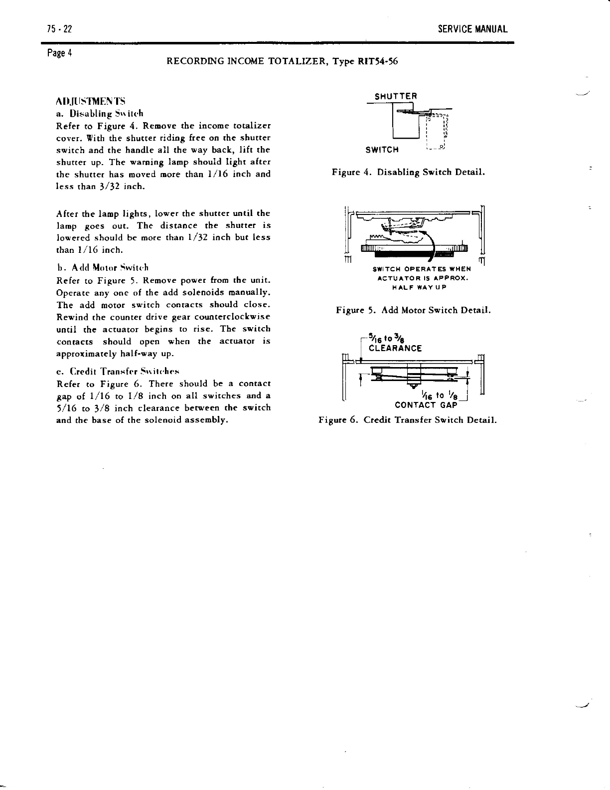
AI)JTIS'IVENTS
a.
Disabling
Srr itch
Refer to Figure 4. Reoove
tbe
income
totalizer
cover. Vith the shutter
ridiog free on ahe shutter
switch
and the
haodle all the
way
back,
lift the
shutter up. The
waroing
laop
should light after
the shutter has ooved
more
thao
1/16 ioch aod
less
than
3
/32 inch.
Afrer the lamp
lights, lower the
shutter uotil the
laop goes out. The
distaoce the
shutter is
lowered
should be rnore
than
l,/J2
ioch but less
than I /16 inch.
b. Add llloror
Switch
Refer to Figure
5.
Remove
power from the uoit.
Operare aoy ooe
of the
add soleooids oaoually.
The add motor
switch cootacts
should close.
Rewind the counter
drive gear counterclockvise
uotil the
actuator begins
to rise. The
switch
contacts should
open
when the
actuator is
apptoximately
half-way
up.
c.
Credit Transfer
Srritt ht s
Refer to Figure
6. There
should be
a contact
gap
of
l/16 to l/8 ioch oo
all switches
and a
1/16
to
3/8
inch clearance
between
the switch
and
the
base of the
solenoid assembly.
RECORDING INCOilIE TOTALIZER,
Type RITt4-r6
SWITCH
Figure
4.
Disabliog Switch Detail.
,,
-_I
1rdt=-.-
..:r=..-
l[l_-H{"ll
lmffi----:rnffi,l
SUITCH
OPERATES
WH
EN
ACTU ATO
R IS APPROX.
HALF WAY
UP
Figure
5.
Add
Motor
Svitch Detail.
54s
tor/s
CLEARANCE
CONTACT GAP
Figure
6.
Credit Traosfer Switch Detail.
SHUTTER
------------------4
Hi I
-T
ll
t5
to 76
]
x

Table of Contents