10.
22
SERVICE IVIAN UAL
Page 12
SELECT-O-MATIC PHONOGRAPH, Model
LSI
coins ale being deposited or
(2)
the customer fails
to release
the selector
keys aftet making
a
selec-
tion.
The tioing relay is energized after the subtract
soleooid
has
eoergized.
Refer to Figure
4.
The
+40
d.c. source in the SCCT is connected directly to the
timing relay via p.in 10 ot
J420L.
A
ground path
is
coopleted through R4203, contacts 4Ul and
pin 1
of
J
4201 and
J
3104
.
Vheo
the tioiog relay energizes,
it closes the
3U1
cootacts
which cooplete
an alteroate ground path
holding itself energized through the letter and
nuober
hold switches
(1S2,
2S2,
4S2).
The tim.ing
relay theo remains energized as long
as
any
letter
or numbet button is held down.
d. Play
Control
and Counter Circuits
The
play
cootrol assembly cootrols the number of
times
dre carriage
is allowed to
scan
back
and
forth
on the tuechanism base. The couoter
assembly
counts the
number
oI selections oade on the
phono-
graph
and is connected in
parallel with the add
solenoid of the
play
cootrol
asseobly. Refer to
Figure
5.
The add solenoid of
the play
cootrol
asseobly
receives its
voltage from the
24-volt
a.c.
supply
in
the
SCC7.
The
ground
side of the add
soleooid
is
connected to
pirr
1 of ahe service
switch
via
pin
3
of
J3102
and P3000. The counter
assembly
receives its voltage from
the
same source
via
pin
9
ol
13102
aod P1000.
Its
grouod
side is
connected
to pin
3
of the service switch,
Both pio
1
and pin
3
are connected to
pio
12 which is con-
nected to
grouod
via the 4U2 cootacts of the sub-
tract solenoid in the UDPU6.
Vhen a
selection
is oade, the subtract solenoid io
the
UDPU6
is eoergized closi[g
the
4U2 cootacts.
This
eoergizes
the add solenoid io the
play
conuol
assenbly aod the couoter asseobly. Each tioe the
add solenoid is
energized,
it mechanically closes a
step svitch which coopletes
a
circuit
to
the
tuech-
aoisr0
ooto! causing
the carriage to begio scanning.
This
switch can only be opeoed by
pulsing
the sub-
ract
soleooid in the SCCT
tvice.
The
subtract solenoid may
be
energized
auto-
oatically rhrough a
play conEol
subtract
svitch in
the I60STU or oanually by using the roaoual credit
svitch oo the service svitch
asseobly, The
play
control
subtract switch is mounted oo
the front of
the
calriage
assembly and
ooves
with it.
Each
time
the
calriage assembly oears
the tight
side
of the
oechanism
base,
a toller
on
the play control sub-
tlact sqitch meets with a stationary
ramp
mouoted
oo the
mechaoism
base. As the carriage
assembly
Doves nearer the right eod of the base,
the roller
ooves
up the raop aod closes the 8M1 cootacts
which
cooplete a circuit to the
play
control sub-
tract solenoid,
The ramp
is
positioned so the car-
riage
will reverse
direction
before the
8Ml
contacts
are allowed to
open. Since it takes two
pulses
of
the subract solenoid to ope! the tnotor
circuit, the
cariage
must scan back and forth twice.
The subract soleooid oay be
energized oanually
by
placiog the
service srv.itch lever
in the OFF
position and
operatiog the
Eaoual credit button
twice.
Each time the credit buttoo is operated,
a
ground circuit to the subtract solenoid is coopleted.
This circuit
is
froo the
ground side of the
subtract
solenoid,
through pin 4 of
13102
and P3000 to
pin
6
of the service
switch. When the
selvice
switch
lever is
io the
OFF
position, pins
5
and
6
are
shorted
together. Pin
5
is connected
to ground via
the
1B2 contacts of the
manual
credit button and
pin
1
of
P3000
and
J1102.
5. SELECTION SY STEM
a, General
This selection systea uses toroidal shaped
mag-
detic cores
(toroids)
of oagoesium ferrite
as the
storage elements, There
are
ooe huodred
and sixty
cores
-
one for each record side
-
arranged
-in
an
electrical
oatrix and housed in the
Tormat
Memory
Uoit.
This
unit,
the electrical selectot, the mech-
anism
cootrol circuits, a
contact
plunger block on
the
oechanism carriage aod the associated elec-
tronjc
circuits comprise the selection system.
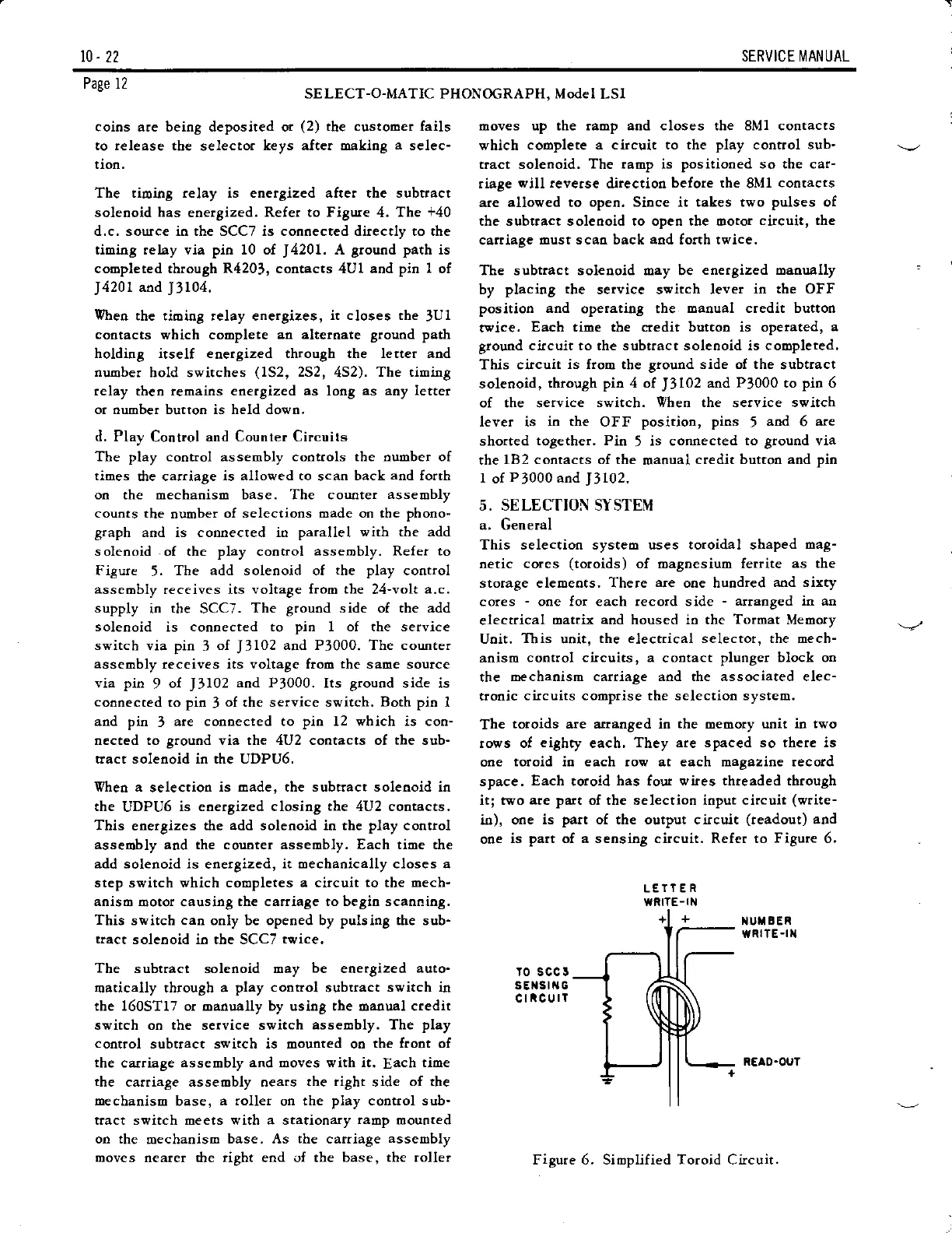
The
toroids
are arranged in
the
oemory urrit
in two
rows of
eighty
each,
They are spaced so there is
one
toroid io each row at each magazine record
space.
Each
toroid
has
four
wies thteaded through
itl two
are part
of the selection input circuit
(write-
io), one
is
part
of the output circuit
(readout)
and
one
is
part
of a sensing circuit. Refer to
Figute
6,
iIUX
BER
wRllE
-t]a
ro scc I
sElstt{G
cticurT
REAO-OUT
Figure 6. Simplified Toroid Circuit.