30.22
SERVICE MAIIUAL
LATCH
RELEASE
Page
2
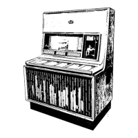
Figute
2.
Latch
Release
Lever
Spring
Detail.
(
l)
Latch Release
Lever
Spting
Refer
to
Figure
2,
Restrain
the
ooveoent of
the
the oumber
release
lever. The force
required to
stalt rlovement of
the solenoid aroature
should
be
5
to
7
ounces.
If
the force required
to
oove
the
atoature
is oore than 7
ouoces, check for
bhds in the
solenoid.
If the force required to
IDove dre arDature is less
than
J
ouoces, re-
place
the
spting.
LATCH EAR
SP
RIN G
TORMAT ELECTRICAL
SELECTOR,
Type
1613-56
6
TO
7
OUNCES HERE
TO
ST
ART MOVEM EN T
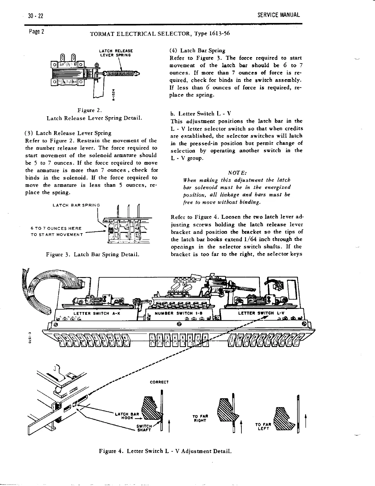
Figure
3.
Latch
Bar
Spriog Detail.
(4)
Latch
Bar
Spriog
Refer
to Figure
J.
The fotce requ.ired to start
Inovement of the lsrch bar sbould be 6 to 7
ounces.
If
oore thao 7 ounceo of fotce
is
re-
quired,
check
for binds ia the
svitch
asseobly.
If
less thaa 6 ounces of force
is
lequired,
re-
place
the spriog.
b. Lerter Switch
L - Y
This adjustment
positions the
latch
bar in
the
L
-
V letter
selector svitch so
that
\r,hen
credits
are
established,
the
selector switches
will latch
in the
pressed-io positioo but
peroit
change
of
selection
by opemtiag anothet
srritch in the
L
-
V
group.
N07
E'..
llhen
making
tbis adiustment tbe latcb
bar solenoid
must be in tbe eaetgized
position, 4ll
linkage
ard barc mus, be
lree
to moue
uitbou,
binding,
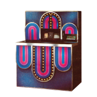
Refer to Figure
4. Loosen the two latch
lever ad-
justing
screws
holding the
latch
release lever
bracket
and
positioo the btacket so
the tips of
the latch
bar books ertend
l/64
itch through
the
opei:ings in the selector switch shafts.
If the
bracket is
too far to the right, the selector
keys
N.
swrrcH,z ll I
sx^fT
u
I
N,
',*N[
,
Figure 4. Letter Switch L
-
V Adjustoent
Detail.