EasyManua.ls Logo

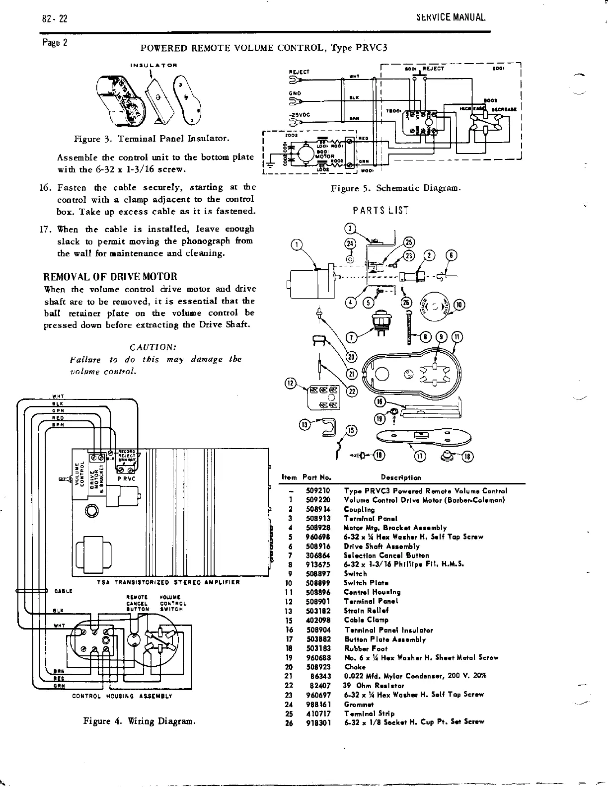
Seeburg LS 1 - Removal of Drive Motor

Seeburg LS 1
126 pages
Print Icon
To Next Page IconTo Next Page
To Previous Page IconTo Previous Page
Loading...
82. 22
StI{VICE I\IANUAL
Page
2
POVERED
REMOTE
VOLUME CONTROL,
Type
PRVC3
IN3\,JLA'Oi
16.
fi.
Figure
5.
Schematic
Diagram.
PARTS L IST
g
(r
-,I@
E.v
F*rn rn m
q v
\l./
\F/
o
\
J tb
t___l tl
.-F
qE
o %---------=--\
.-
:_r'
r
-."0-@
O W
coti rRoL H0rJ9rNc ls€E
BLY
Figure
4. Viriog Diagram.
%$s
Figute
3.
Teunioal Panel Insulator.
Assemble the
contol unit to dre bottom
plate
with the
6-32
x 1-3,/16 screw.
Fasteo the cable
securely, starting
at
6e
cootrol with
a
clamp
adjaceot
to the cootrol
bor. Take
up excess cable
as it is fastened.
Vheo the
cable is iastalled,
leave eoough
slack
to
peroit
ooving the
phonograph from
che wall for maiotenaoce
and cleaning'
REMOVAL OF DRIVE
MOTOR
Vheo
the voluoe control &ive
motor
aad &ive
shaft
are
to be
reooved,
it is essential
that the
baII retainer
plate
on the
volume control
be
pressed
dovn before
extracting the Drive
Shaft.
CAUTION:
Faihre
to do
this may damage
lbe
oolame conlrol,
-
509210
I
5092m
2
5089
t,a
3
5089t3
,l
506928
5
90698
6 508916
7 30686i1
8 9t3675
9
500897
t0
508899
I I
508896
12
508901
t3 503t82
t5
a02l)9t
t6
50890,(
17
5036E2
t8
503t8
19 960688
20 5r)8923
21
86343
22
A21o7
23 9&697
2,( 9E816l
25 110717
26
gt8tr)l
Typ. PRVC3 Powrrcd Rcmorc Volurnr Coatrcl
Volum.
Contiol Drlvc Motor
(Borbcr-.Cohmon)
Coupllng
Trrmlnol Poncl
Moro? Mrt,
Blocl.t Arr.mbly
6-32tVlitx
Worhrr
tl.
Solf Top lcrrw
Drlvc Shoh
Arrcmbly
5rlrcrlon
Coneol
Bution
632 x
I3,/16 Phllllpr
Fll. H.M.5'
Swlrch
Swltch Plot.
Control lloutlns
Trrmlnol
Panrl
str.ln R.ll.l
Coblo
Clomp
T.rmlnol
Pon.l ln.uloior
Burton P
lot.
At..mbly
Rlbb* Foor
No.
6
x
%
Hrx Worhcr H.
Sh..t |,t.tol SG'.w
Chokc
0.022 trttd. ltylor
Cond.n..r,
200 Y.
2@o
39 Ohn Rorlrror
&32 x 7r
Hcx
worhu H. 5oll
Top Scrcw
Gromm.t
T.lrtllnol
Srrlp
&,32 r
t/8 Sockor
H. Cup
Pt.
3or Scrrw

Table of Contents