80-?2
SERVICE MANUAL
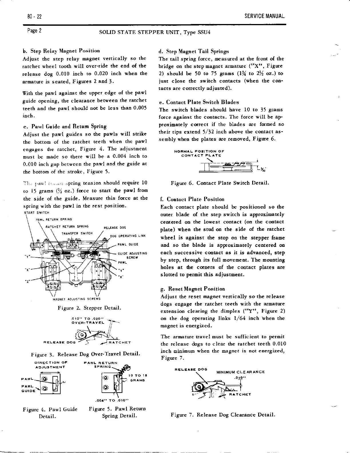
b.
Step
Relay
Nlagnet
Position
Adjust the step
relay
maSDet
veltically so
the
ratchet
wheel tooth will
over-ride
the end of tbe
release dog 0.010
ioch
to 0.020
inch when the
armature is seated,
Figures
2 and
3.
Vith the pawl
against the
upper edge
of the
pawl
guide opening,
the
clearaoce
berweeo the
ratchet
teeth and the
pawl should
not be less
than 0.005
ioch.
c. Pawl Guide
and Return
Spring
Adiust the
pawl guides
so
the
Pawls
will strike
the bottom of
the ratchet
teeth
when the
Pavl
engages
dre ratchet,
Figure 4.
The adjustmeot
must
be Dade so
there vill be
a 0'004
ioch to
0.010 inch
gap between
the
Pawl
aod the
guide at
the bottom
of rhe stroke,
Figure
5.
T'l:,
1aa,l
r, ...rr ipriog
tension
should
require 10
to
15
Brams
(fi
oz.)
fotce to start
the
pawl from
the side of
the
8uide.
Measure
this force at
tbe
spriog wich che
pavl
in
the rest
Position.
PAVTL
FETI]RN SPFING
SOLID
STATE STEPPER UNIT, Type
SSU4
d. Step Magnet
Tail Springs
The
tail spring
force, oeasured at the front of
the
bridge on the step Dagret
armatute
("X",
Figure
2) should be
,O
to
75
graos
(lVt
to
2%
oz,)
ro
iust
close the
switch contacts
(wheo
the
con-
tacts are c orrectly adiusred).
e. Contact
Plate Switch Blades
The
svitch
blades should have
10 to
35
graos
force against the contacts.
The force
will
be
ap'
prorioately cqtect
if the blades are formed
so
rhe.ir rips extend
5/32
inch above
the co[tact as-
seobly when the
plates are removed,
Figure
6'
NORMA L
POSIIION OF
CONIACT
PLAYE
\
Figure 6, Contact
Plate
Switch
Detail.
f. Contact
Plate Position
Each contact
plate
should be positioned so
the
outer blade of
the step switch is approrimately
cenreled
on
the lowest cootact
(on
the cootact
plate) vhen the stud oo the side
of the ratchet
wheel
is agaiost the stop on the
stepper frame
and so the blade is approximately
centered oo
each successive
cootact as it is advanced,
step
by
step,
through its full movemeot. The mouoting
holes at dre coroers of the cootact
plates are
slotted to petoit this adiustment.
g. Reset Magnet
Position
Adjust the reset
rvrgoet
vertically so
the release
dogs engage
the ratchet teeth
w-ith
the armature
extension clearing the dimples
("Y",
Figure 2)
on the dog operating l,oks
l/64 inch
rrhen
the
magnet
is energized,
The aroatute travei oust be sufficient
to peroit
the release dogs
to
clear
the tatchet teeth 0.010
inch oinioum
when
the magnet
is not energized,
Figure 7,
Page 2
iATCHE'I iETIJRTI SPFIN6
MA6NE'I
AOJUSI NG SCREWS
Figure 2.
Steppet
Detail.
Figtte
3.
Release
Dog Over'Travel
Detail'
Figure
5.
Pawl
Returo
Spring
Detail.
CUIOE
Figure 4,
Pawl Guide
Detail.
MIN IMUM CLE AR AN CE
Figure
7.
Release Dog Clearaoce Detail.