60.
22
SERVICE MANUAL
Page
2
"'o''Y'
t,,
l
'i,
$.
UNIVERSAL DUAL PRICING
UNIT, Type UDPU6
AOD ARM
ASSE|.'LY
OE'ET{T
AOO ART
STOP
BRACXET
.\
.ol5 To .0lo
[rcn
\_
0At wrTn
A0D
30LaIOt0
EXEiStZE0
Figure
4. Solenoid Adjustoeot
Detail.
ciE0rT
WHEEL
DIME 3TO P
8
RACKET
tcaEw
r'l
L sr
POSTTtOt{
TO
A00
2
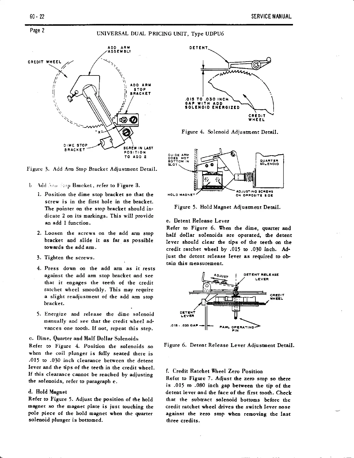
Figure
3.
Add
AnD Stop Btacket Adjustoeot Detail.
L
{d(l
'..,,,
.;,'p
Bmcke!
,
refer to I'igure 3.
l. Position the dioe stop
bracLet so
that
dre
sctew is in
the first
hole io
the bracket.
The
poioter
or
the stop bracket should in-
dicate 2 oo its markings. This will
provide
an
add I functioo.
2.
Loosen
the screws on the add arm
stop
bracket aod slide it as
far
as
possible
towatds
dre
add aro,
3.
Tighteo the
screws.
4.
Press
dovn oo the add arm as it
rests
against
the add arm stop
bracket
and
see
thar ir engages rhe reeth
of
the
credit
ratchet
wheel smoo&ly. This may require
a
slight readjusmeot of the add arm
stop
bracket-
5.
Energize aad release the
dioe
solenoid
oaoually aod
see that the
credit wheel ad-
varlces
ooe tooth. If not,
repeat this step.
c. Dime,
Quarter
and
Hal{ Dollar Solenoids
Refer
to Figure
4.
Positioo
the
solenoids so
when
the
coil
plunger
is folly seated
there is
.015
to .030 inch
clearance betveen
the detent
lever and
the tips of the
teeth in the
credit vheel.
If this
cleataoce
caonor be reached
by adlustiog
the solenoids,
refer to
paragraph
e,
d. Hold
Magnet
Refer
to Figure
5.
Adiust the
positioo
of the
hold
EaSoet
so the
magoet
plate
is
iust
touching
the
Pole
piece
of
the hold magnet when
the
quarter
soleooid
plunger
is
bottooed.
Figure
5,
Hold
Magoet Adiustoeut
Detail.
e. Detent Release Lever
Refer to Figure
6.
Vhen
thc dime,
quarter
and
half dollar solenoids are
operated, tlle detent
lever
should clear dre tips of the
tecth oa tbc
credit
ratchet vheel by .01, to .030 ioch. Ad-
iust
the detent release lever as
required to ob-
taitr this oeasurement.
SLOT
AOJ u
3r
r.rc
lcraws
or{ orpot
Yl
!
oa
.013-
t
"^..
";1,^'>=
Figure
6.
Detent Release
Lever Adjustrlent
Detail.
f. Credit Ratchet Wheel
Zero Position
Refer
to
Figure
7,
Adiust
dre zeto stop
so there
is
.01, to .080
inch gap
between fie tip of
dre
detent lever and
dre face of the
fitst tooth. Check
that
the subtract solenoid
bottoms beiore tbe
credit ratchet
wheel
drives the switch lever oose
against
the ze.o
srop wheo
removing the last
three
credits.