100 User Manual
INSTALLATION AND REMOVING
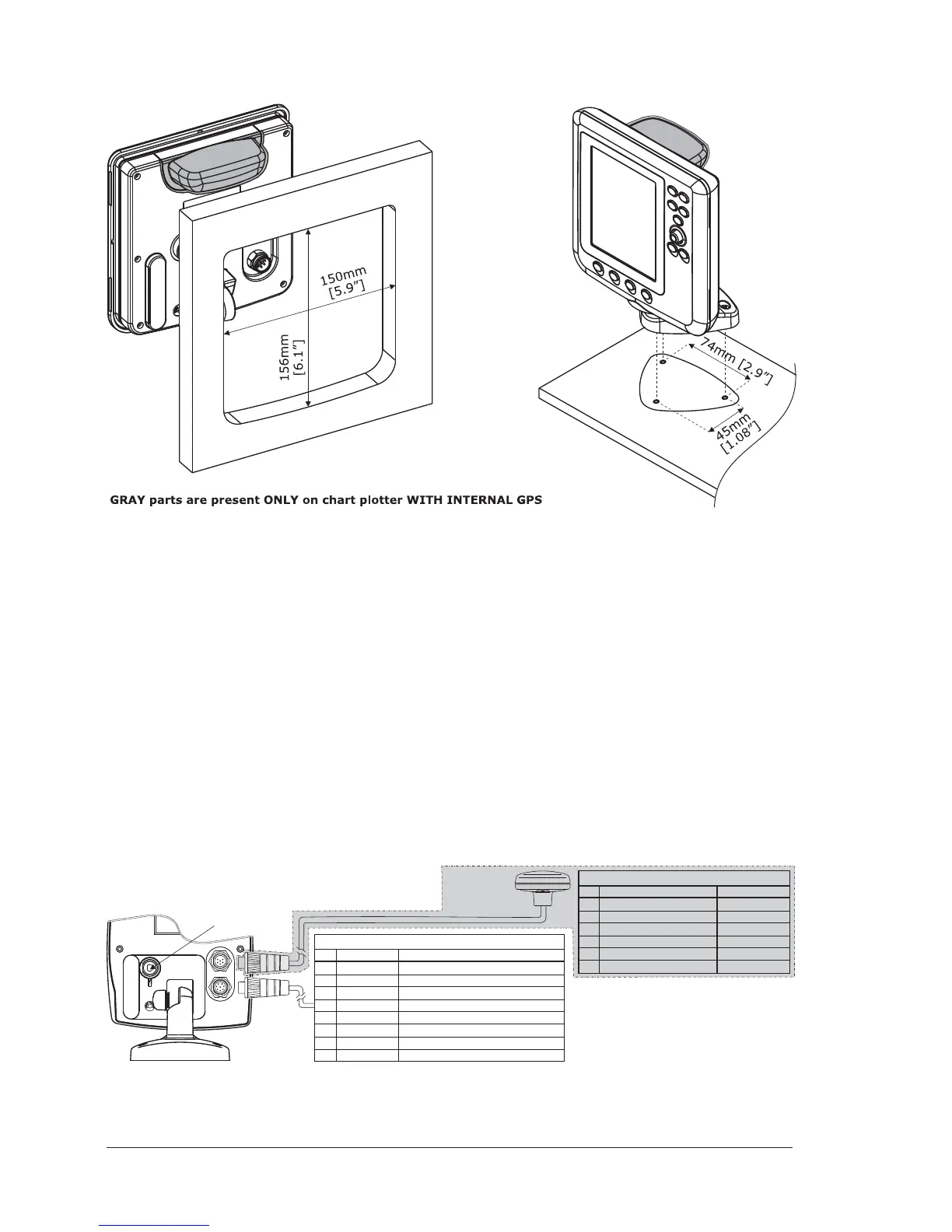
It is possible to install this TECHMARINE instrument in "Flush Deck" mode, with
space saving regard to the instrument panel plan.
To make the "Flush Deck" installation it is necessary to permanently remove the
silicon gasket between rear and front, placed around the chart plotter.
To remove the gasket, lay the chart plotter on its front side, to pay attention do
not damage LCD and keyboard, and use a sharpening blade.
Put the blade between the gasket and the lateral side of the rear, to turn the chart
plotter.
Warning
Do not pull the gasket during cut operation, to avoid compromising the chart
plotter watertight seal.
EXTERNAL WIRING
M
IN
I
B
U
S
B
co
n
n
e
cto
r
RED
GREEN
BROWN
NC
NC
BLACK/YELLOW/SHIELD
CA
BLE
COLOR
+10-35Vdc
OUTPUT 3+
INPUT 3+
GND/COMMON
FU
N
C
TIO
N
1
2
3
4
5
6
PIN
SMART GPS
sensor
CABLE COLOR
BLACK
RED
WHITE
GREEN
GRAY
YELLOW
BROWN
BLUE
FU
N
C
TIO
N
PWR-/GND/COMMON
PWR
+
(10-35 Vdc)
INPUT 1+
COMMON
OUTPUT 2+
OUTPUT 1+
INPUT 2+
EXT. ALARM
SIGNAL
(to GND when ON
)
1
2
3
4
5
6
7
8
PIN
GRAY parts are present ONLY on
chart plotter WITH GPSEXTERNAL
POWER & I/O CONNECTOR/CABLE
GPS CONNECTOR/CABLE
 Loading...