Doc. 177/5250x
Rev A
3-2
Connecting the Display
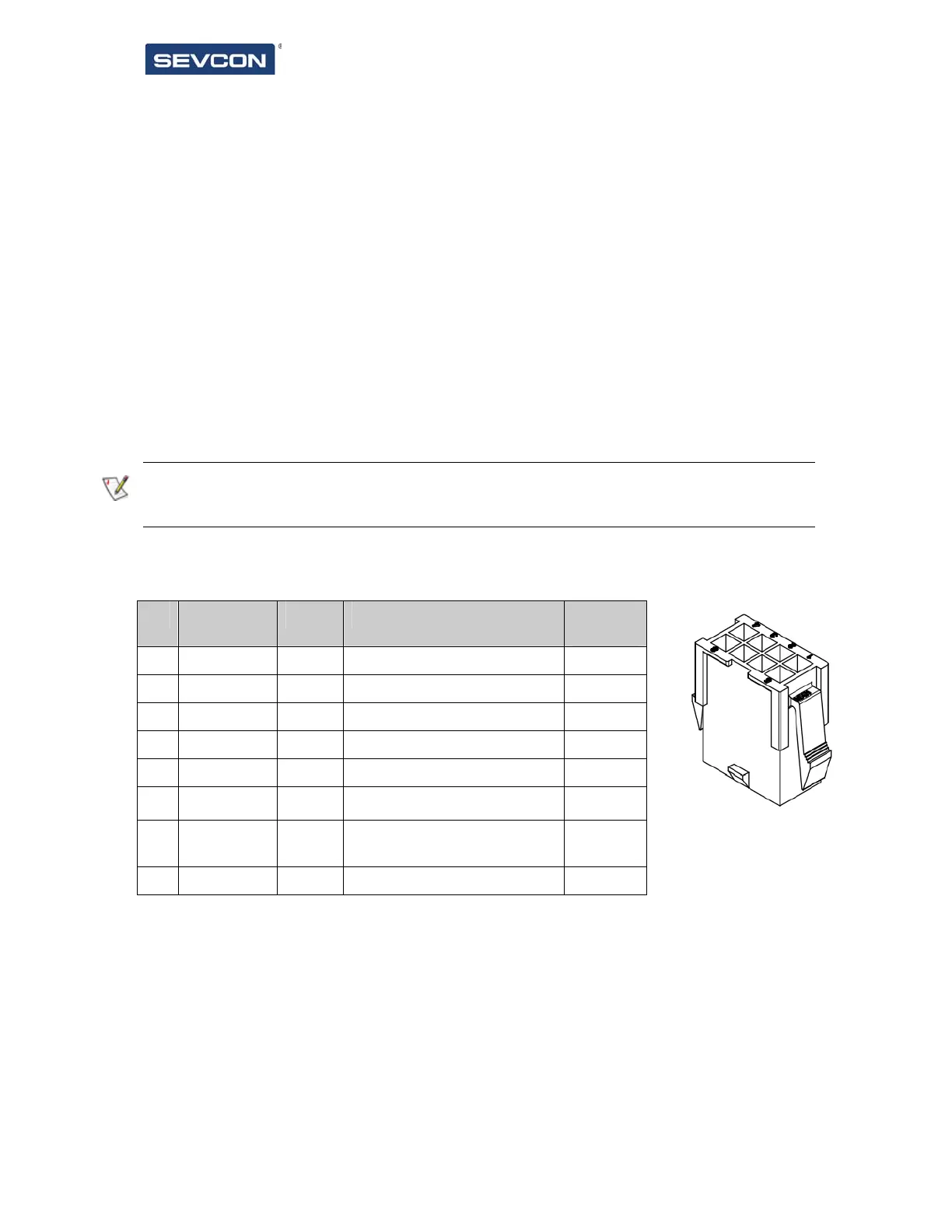
Connector
The display is supplied as standard with an 8 way Molex connector.
CAN bus termination
The display is designed to be permanently connected to a single or multi node CAN bus. To
assist with wiring on the vehicle the display includes a CAN termination resistor which can be
used as required to achieve the correct bus termination.
If the display fails to detect a standalone device then you should check that the CAN bus has
correct termination
Signal connections
Pin Name Type What to connect Maximu
m rating
1 +24V power Power Not connected 35V
2 Gnd Power +24Volt supply return -35V
3 CAN High Comms CAN High 35V
4 CAN Low Comms CAN Low 35V
5 CAN High Comms CAN High 35V
6 CAN Low Comms CAN Low 35V
7 CAN Term Comms
Link to pin 6 to enable 120
termination
8 N/C Not connected
Table 1 Connector pin out and wiring information
Pins are protected against short-circuits to the battery positive or negative voltages.
CAN High and CAN Low connections are duplicated to enable daisy chaining of CAN nodes.