Fault Finding
______________________________________________________________________________
MillipaK PUMP Controller Manual Page 43 07/11/05
Fault Clearance
Any fault indication will be cleared by re-initiating the start sequence after the cause of the fault
has been removed. Some faults may only be cleared by re-cycling the key-switch.
Using Status and Test Menus
The status and test menus which are available on the calibrator interface can be used to help
pinpoint wiring faults or device failures.
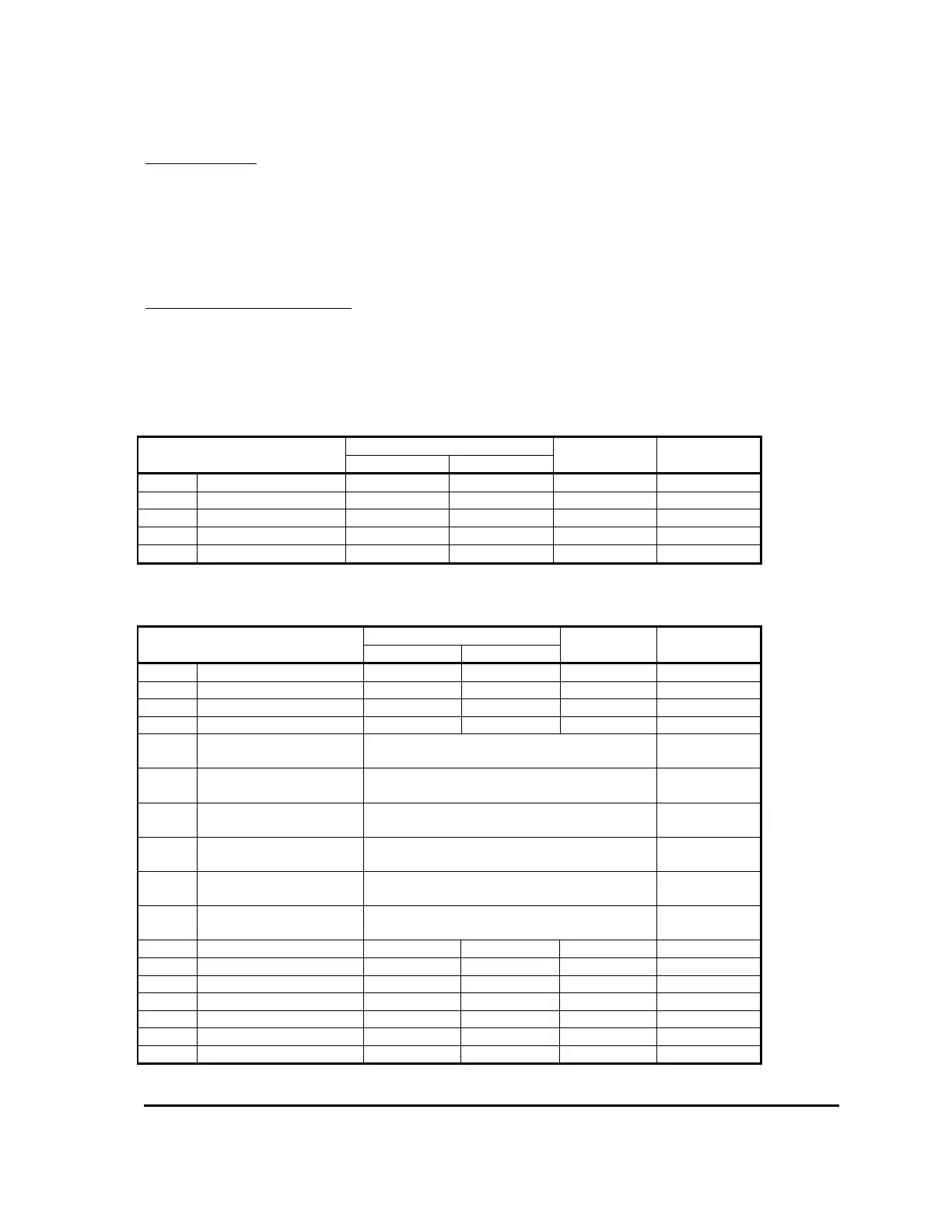
System voltages and currents are available on the following menu items:
Item Range Resolution Display
Minimum Maximum Format
15.01 Battery Voltage 0.0V 63.9V 0.1V
000.0
15.02 Capacitor Voltage 0.0V 63.9V 0.1V
000.0
16.01 Motor Voltage 0.0V 63.9V 0.1V
000.0
17.01 Motor Current 0A 1000A 5A
x000
18.01 Temperature
-30°C 225°C 1°C
x000
Controller analogue and digital input status can be read from the following menu items:
Item Range Resolution Display
Minimum Maximum Format
19.01 Accel 1 Demand 0% 100% 1%
x000
19.02 Accel 1 Voltage 0.00V 5.00V 0.02V
00.00
19.03 Accel 2 Demand 0% 100% 1%
x000
19.04 Accel 2 Voltage 0.00V 5.00V 0.02V
00.00
19.05 Digital 1 (Pin 2) Open
Closed
x1.OP
x1.CL
19.06 Digital 2 (Pin 3) Open
Closed
x2.OP
x2.CL
19.07 Digital 3 (Pin 4) Open
Closed
x3.OP
x3.CL
19.08 Digital 4 (Pin 5) Open
Closed
x4.OP
x4.CL
19.09 Digital 5 (Pin 6) Open
Closed
x5.OP
x5.CL
19.10 Digital 6 (Pin 7 (switch)
or Pin 11 (analogue))
4
Open
Closed
x6.OP
x6.CL
19.11 S/W Version 00.00 19.99 0.01
00.00
19.12 S/W Sub-Revision 00 99 1
xx00
19.13 SN Date Code 0100 1299 1
0000
19.14 SN ID 1 00 99 1
xx00
19.15 SN ID 2 00 99 1
xx00
19.16 Pers Checksum 0 255 1
000
19.17 System State 0 13 1
x00