Installation Wiring/Light
______________________________________________________________________________
MillipaK PUMP Controller Manual Page 9 07/11/05
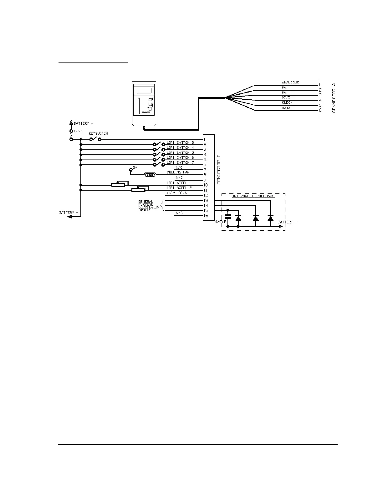
MillipaK Pump Light Wiring
NOTES:
The line and auxiliary contactors coils are wired to B+, on the switched side of the key-switch.
The second analogue input on pin 11 is also available for use as a digital input. See system
configuration section for how to configure the second analogue input as a digital switch input.
Pin 12 on the Core and Standard HP variants is available for 100mA supply, typically used for
(but not limited to) accelerator modules.
Pins 13,14 & 15 are general-purpose suppression connections and may be used to suppress spikes
generated by contactors opening / closing. The internal configuration is shown below:
Pin 16 on the Core and Standard HP variants is used to select FLASH memory program update
mode and should normally be left unconnected.