5
Electrical installation
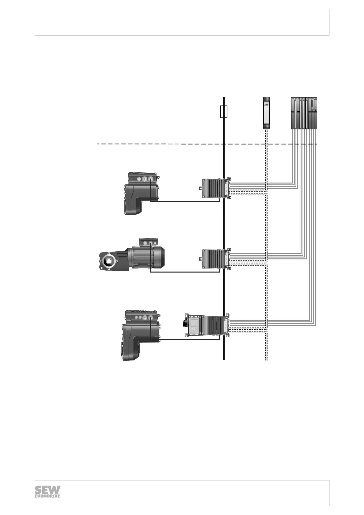
Installation topology (example: standard installation)
Operating Instructions – MOVIMOT
®
flexible
57
5.4 Installation topology (example: standard installation)
The following figure shows a basic installation topology with the device:
Safety
relay
Supply system
Control
Back-up
fuse/line
protection
Control cabinet level
Field level
[4] Binary control signals
[3] STO
Supply system
[2] MMF1../DBC..
[2] MMF1../DBC..
[2] MMF3../DBC..
[1] MGF..-DSM-C
[1] ..DRN...
[1] MGF..-DSM-C
29494370827
[1] Connected drive units with/without digital interface
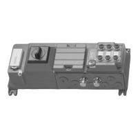
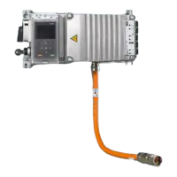
[2] MOVIMOT
®
flexible with DBC.. electronics cover
[3] The STO cable between the safety relay and the last decentralized frequency in-
verter may not be longer than100m.
[4] Control using up to 4 binary signals and 1 analog signal
29129451/EN – 12/2019
 Loading...