Do you have a question about the SEW-Eurodrive MOVIMOT flexible MMF1 C/DBC Series and is the answer not in the manual?
| Brand | SEW-Eurodrive |
|---|---|
| Model | MOVIMOT flexible MMF1 C/DBC Series |
| Category | DC Drives |
| Language | English |
Emphasizes complying with safety notes during startup and lists warnings.
Explains Easy mode and Expert mode for device parameterization.
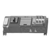
Provides an overview of control elements on the electronics cover, including potentiometers and DIP switches.
Explains how to use potentiometer f1 to adjust speed setpoint f1, with scaling graph.
Details using potentiometer f2 to adjust speed setpoint f2, including scaling graph.
Describes setting acceleration/deceleration setpoint t1 using the potentiometer.
Provides an overview of DIP switches S1, S2, and S3 and their functions.
Shows how to perform startup via DIP switch S3 using motor selection tables.
Outlines startup steps in Easy mode and Expert mode, including a checklist.
Explains intuitive startup using the CBG21A keypad guided by symbols and display.
Explains intuitive startup using the CBG11A keypad and notes limitations with encoders.
Details configuration of digital inputs and relay output in Easy and Expert modes.
Explains setpoint scaling for analog input AI1 based on operating mode and scaling parameters.
Provides important notes on disabling DynaStop® for startup purposes.
Explains drive unit behavior based on digital input configurations and status.
Guides on using MOVISUITE® for manual device operation via the manual mode function.
Explains the DynaStop® function, its limitations, impermissible uses, and torque specifications.
Explains how to enable and configure the function for releasing the brake/DynaStop® via control signal.
Discusses DynaStop® usage with STO function, warnings, and safety relevance.
Guides on evaluating fault messages using MOVISUITE® parameter tree and fault status.
Lists fault messages and their possible parameterizable responses.
Provides a detailed fault/error table listing LED status, fault codes, subfault codes, meaning, and measures.
Provides notes and procedures for replacing electronic covers and devices.
Provides information on sending devices for repair and required information.
Provides recommendations for selecting motors and inverters based on characteristic curves.
Provides motor/inverter assignments for MOVIMOT® flexible and technical data for DR.. motors.
Details motor/inverter assignments for DR2S motors at 4 kHz PWM frequency.
Provides motor/inverter assignments for DRN.. motors at 4 kHz PWM frequency.
Lists technical data for CMP.. motors, including speed, torque, current, and mass.
Shows motor/inverter assignments for CMP.. motors at 4 kHz PWM frequency.
Provides motor/inverter assignments for CMP.. motors at 8 kHz PWM frequency.
Lists technical data and assignments for MOVIGEAR® classic motors with W connection type.
Provides motor/inverter assignments for MOVIGEAR® classic motors at 4/8 kHz PWM frequency.
Explains inverter selection based on output current, torque characteristics, and thermal monitoring functions.
Describes load cycles for selecting asynchronous and servomotors, detailing overload capacity at 4 kHz PWM.
Explains derating due to rotary field frequency, installation altitude, and ambient temperature.
Covers information on ambient temperature, technical data, and selection criteria for braking resistors.
Lists general technical data for input and output parameters of MOVIMOT® flexible.
Describes HV brake control and DC 24 V brake control types, supported brakes, and control modes.
Provides an overview of braking resistors and their possible use in regenerative mode.
Illustrates the current-carrying capacity of the BW1 braking resistor and provides a calculation example.
Details technical data and dimensions for external braking resistors BW100-005/K-1.5, BW150-003/K-1.5, and BW...-T series.
Explains the safety technology of MOVIMOT® flexible, including safe states and concepts.
Describes the drive unit's capability for Safe Torque Off and its connection to external safety devices.
Covers STO (Safe Torque Off) and SS1(c) (safe stop 1) drive safety functions and their sequences.