11
Technical data and dimension sheets
Braking resistors
Operating Instructions – MOVIMOT
®
flexible
315
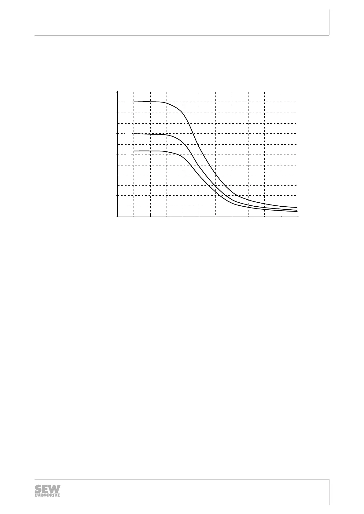
11.5.2 Integrated BW1 braking resistor
The following diagram shows the current-carrying capacity of the BW1 braking resistor
per braking operation:
200
300
400
500
600
[J]
[1]
[2]
[3]
0
100
01050 100 200 500 1000 2000 3000 4000 5000 6000
[c/h]
25291390987
[1] Deceleration ramp 10s
[2] Deceleration ramp 4s
[3] Deceleration ramp 0.2s
c/h Cycles/hour
Calculation example
The known values are:
• Average braking power: 144W
• Deceleration ramp: 2s
• 200 brake applications per hour
Calculating the energy from the power of the deceleration ramp:
W P t
W W s
W J
= ×
= ×
=
144 2
288
25296909835
For the deceleration ramp of 2s, you can use deceleration ramp [3] (0.2s) in the dia-
gram. Use the characteristic curve with the shorter deceleration ramp because a
shorter deceleration ramp means more braking energy.
The diagram permits 290 J of braking energy for the 0.2 s deceleration ramp and
200cycles per hour. In this case, the required 288J can be dissipated via BW1.
29129451/EN – 12/2019
 Loading...