5
Electrical installation
Terminal assignment
Operating Instructions – MOVIMOT
®
flexible
60
Assignment
Terminal No. Name Marking Function
Connection depending on the connec-
tion unit
1)
Option /CO
2)
Option /DI
X2_A
Terminals for motor,
brake and temperature
sensor
D Brake D White Connection
Brake D
Connection
Brake14
C Brake C White Connection
Brake C
Connection
Brake13
B Brake B White Connection
Brake B
Connection
Brake15
A1 Brake A White Connection
Brake A
Connection
Temperature sensor
(Temp+)
T2 – White
Reserved
Connection
Temperature sensor
(Temp-)
U U Gray Motor connection, phase U
V V Gray Motor connection, phase V
W W Gray Motor connection, phase W
1) See chapter "Type designation of the connection unit".
2) For more information refer to chapter "Bulk cables" > "Brakemotor cables for motors with digital interface (MOVILINK
®
DDI)" > "Con-
necting the bulk cables".
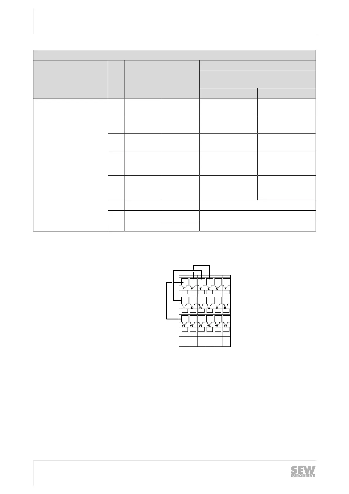
The following figure shows the factory-installed jumpers at the X9 terminals:
1 2 3 4
11 12 13 14
21 22 23 24
5 6
15 16
25 26
X9
29006177419
These jumpers are not present in the following designs:
• Designs with plug connectors with STO function.
For additional information, refer to chapter "Functional safety".
29129451/EN – 12/2019
 Loading...