15
Product Version 1.0 | Revision D | Released 2022-06-20
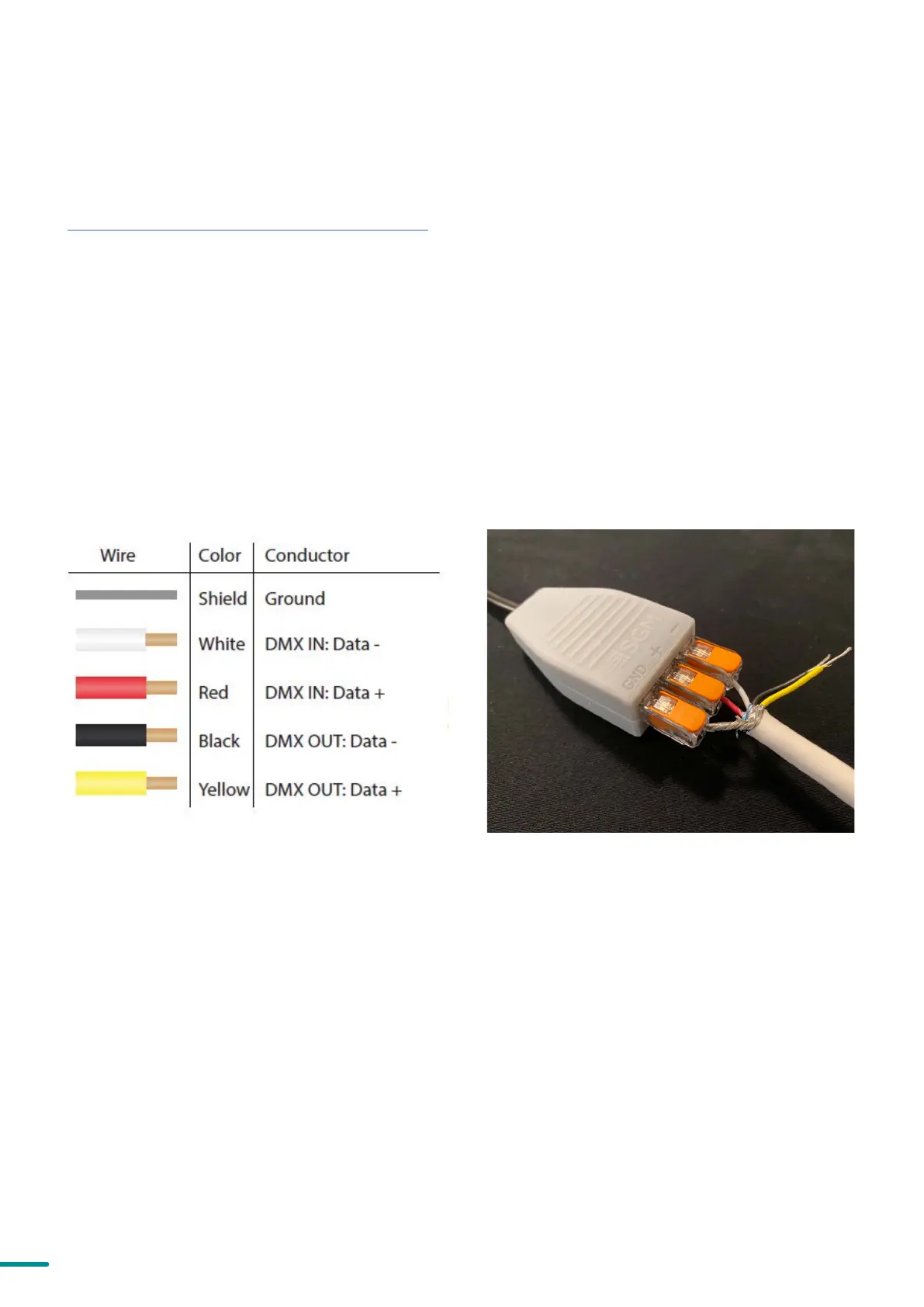
Figure 9: Connecting data to USB up-loader cable for POI fix-
tures
Figure 8: Data wiring guide for setup
CONNECTING TEMPORARY SIGNAL
The fixture is compatible with DMX512 (ANSI E1.11 – 2008) only. It can be connected using either the SGM POI up-load-
er cable, or via the fixture’s built-in CRMX wireless receiver system.
STEP 1: Download and install the SGM RDM Addressing tool.
< https://sgmlight.com/products/rdm-addressing-tool >
STEP 2: Connect the bare end data cable to the POI Up-loader cable for POI fixtures.
STEP 3: Connect the USB up-loader cable for POI fixtures to a computer with a USB Type-A port.
STEP 4: Launch SGM RDM Addressing Tool. Click Full Discovery and look for the green light to illuminate on the fix-
ture. Configure all settings as needed.
Step 5: Disconnect up-loader cable from computer, then disconnect up-loader cable from fixture.
Repeat Steps 2-5 for more fixtures. Multiple fixtures can be addressed and configured. Contact your SGM representa-
tive for more information on multiple fixture addressing.
PLEASE NOTE! AT A MINIMUM, ALL FIXTURES WILL NEED TO BE GIVEN A DMX ADDRESS AND DMX PERSONALI
TY IN ORDER TO PATCH AND PROGRAM ON A CONTROLLER. REFER TO MANUALS FOR MORE DETAILS.
 Loading...