Home
Shini
Water Heater
STM-W Series
Shini STM-W Series User Manual
5
of 1
of 1 rating
107 pages
Give review
Manual
Specs
To Next Page
To Next Page
To Previous Page
To Previous Page
Loading...
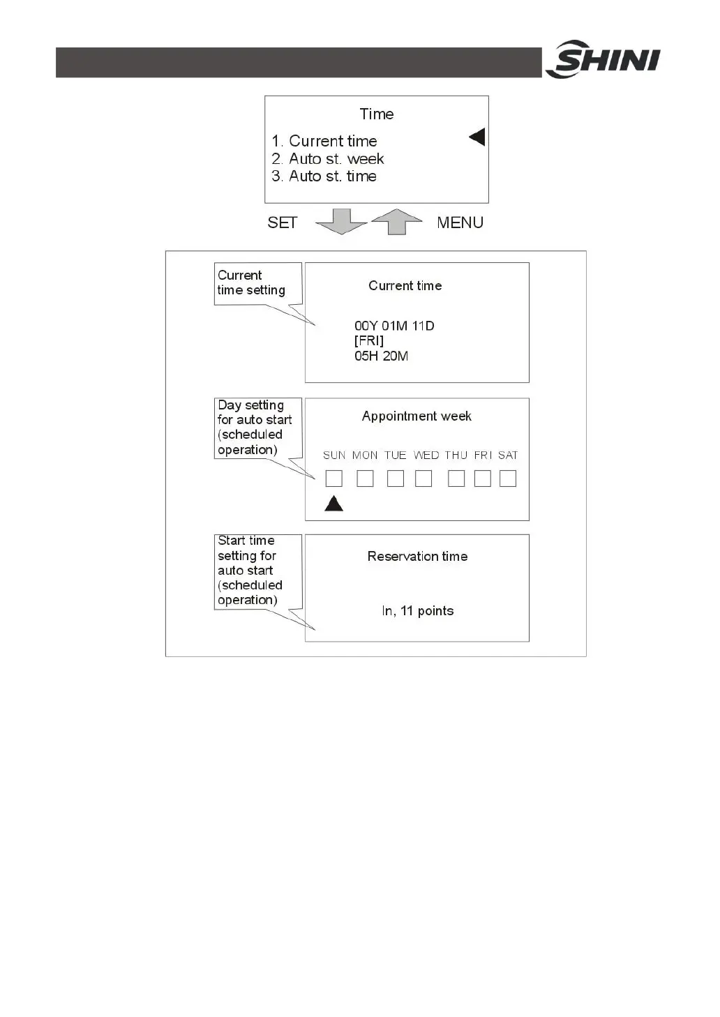
91(107)
Pi
c
t
u
r
e
4
-
9
:
T
i
m
e
S
e
tti
n
g
11
)
P
r
e
ss
M
E
NU
k
e
y
t
o
r
e
t
u
r
n
t
o
m
e
nu
sc
r
ee
n
,
p
r
e
ss
◄
/
►
k
e
y
t
o
s
e
l
e
c
t
c
o
m
m
u
n
i
c
a
t
i
o
n
s
e
tt
i
n
g
,
p
r
e
ss
S
E
T
k
e
y
t
o
e
n
t
e
r
s
e
tt
i
n
g
sc
r
ee
n
,
s
e
e
p
i
c
t
u
r
e
be
l
o
w
.
I
f
c
o
m
m
un
i
c
a
t
i
o
n
f
u
n
c
t
i
o
n
i
s
s
e
l
e
c
t
ed
a
s
an
op
t
i
o
n
,
c
u
s
t
o
m
e
r
s
s
hou
l
d
s
e
t
c
o
m
m
un
i
c
a
t
i
on
pa
r
a
m
e
t
e
r
s
b
a
s
e
d
o
n
a
c
t
u
a
l
n
e
ed
s
.
90
92
Table of Contents
Default Chapter
3
Table of Contents
3
1 General Description
9
Coding Principle
10
Feature
10
Technical Specifications
12
Specification
12
Pump Performance
13
Reference Formula of Mould Controllers Model Selection
13
Safety Regulations
14
Safety Signs and Labels
14
Signs and Labels
15
Operation Regulations
16
Exemption Clause
17
2 Structure Characteristics and Working Principle
18
Main Functions
18
Working Principle
18
Picture 2-1:STM-W Working Principle
18
Assembly Drawing
20
Assembly Drawing (STM-607W/910W)
20
Picture 2-2:Assembly Drawing (STM-607W/910W)
20
Parts List (STM-607W/910W)
21
Assembly Drawing (STM-1220W)
22
Picture 2-3:Assembly Drawing (STM-1220W)
22
Parts List (STM-1220W)
23
Assembly Drawing (STM-2440W)
24
Picture 2-4:Assembly Drawing (STM-2440W)
24
Parts List (STM-2440W)
25
Assembly Drawing (STM-3650W)
26
Picture 2-5:Assembly Drawing (STM-3650W)
26
Parts List (STM-3650W)
27
Pump
28
Picture 2-6:Pump
28
Electrical Diagram
29
Main Circuit (STM-607W~1220W 400V)
29
Picture 2-7:Main Circuit (STM-607W~1220W 400V)
29
Control Circuit (STM-607W~1220W 400V)
30
Picture 2-8:Control Circuit (STM-607W~1220W 400V)
30
Electrical Components Layout (STM-607W~1220W 400V)
31
Picture 2-9:Thermocouple and Terminal Layout (STM-607W~1220W 400V)
31
Electrical Components List (STM-607W~1220W 400V)
32
Table 2-6:Electrical Components List (STM-910W 400V)
33
Table 2-7:Electrical Components List (STM-1220W 400V)
34
Main Circuit (STM-607WA~1220WA 400V)
35
Picture 2-10:Main Circuit (STM-607WA~1220WA 400V)
35
Control Circuit (STM-607WA~1220WA 400V)
36
Picture 2-11:Control Circuit (STM-607WA~1220WA 400V)
36
Electrical Components Layout (STM-607WA~1220WA 400V)
37
Picture 2-12:Thermocouple and Terminal Layout (STM-607WA~1220WA 400V)
37
Electrical Components List (STM-607WA~1220WA 400V)
38
Table 2-9:Electrical Components List (STM-910WA 400V)
39
Table 2-10:Electrical Components List (STM-1220W 400V)
40
Main Circuit (STM-607W-D/910W-D 400V)
41
Picture 2-13:Main Circuit (STM-607W-D/910W-D 400V)
41
Control Circuit (STM-607W-D/910W-D 400V)
42
Picture 2-14:Control Circuit 1(STM-607W-D/910W-D 400V)
42
Picture 2-15:Control Circuit 2(STM-607W-D/910W-D 400V)
43
Electrical Components Layout (STM-607W-D/910W-D 400V)
44
Picture 2-16:Electrical Components Layout (STM-607W-D/910W-D 400V)
44
Thermocouple and Terminal Layout (STM-607W-D/910W-D 400V)
45
Picture 2-17:Thermocouple and Terminal Layout (STM-607W-D/910W-D 400V)
45
Electrical Components List (STM-607W-D/910W-D 400V)
46
Table 2-12:Electrical Components List (STM-910W-D 400V)
47
Main Circuit (STM-2440W 400V)
48
Picture 2-18:Main Circuit (STM-2440W 400V)
48
Control Circuit (STM-2440W 400V)
49
Picture 2-19:Control Circuit (STM-2440W 400V)
49
Thermocouple and Terminal Layout (STM-2440W 400V)
50
Picture 2-20:Thermocouple and Terminal Layout (STM-2440W 400V)
50
Electrical Components List (STM-2440W 400V)
51
Main Circuit (STM-3650W 400V)
52
Picture 2-21:Main Circuit 1(STM-3650W 400V)
52
Picture 2-22:Main Circuit 2(STM-3650W 400V)
53
Control Circuit (STM-3650W 400V)
54
Picture 2-23:Control Circuit (STM-3650W 400V)
54
Electrical Components Layout (STM-3650W 400V)
55
Picture 2-24:Electrical Components Layout (STM-3650W 400V)
55
Electrical Components List (STM-3650W 400V)
56
Main Circuit (STM-3650WA 400V)
57
Picture 2-25:Main Circuit 1(STM-3650WA 400V)
57
Control Circuit (STM-3650WA 400V)
58
Picture 2-26:Control Circuit (STM-3650WA 400V)
58
Electrical Components Layout (STM-3650WA 400V)
59
Picture 2-27:Electrical Components Layout (STM-3650WA 400V)
59
Electrical Components List (STM-3650WA 400V)
60
Main Circuit (STM-607W~1220W 230V)
61
Picture 2-28:Main Circuit (STM-607W~1220W 230V)
61
Control Circuit (STM-607W~1220W 230V)
62
Picture 2-29:Control Circuit (STM-607W~1220W 230V)
62
Electrical Components Layout (STM-607W~1220W 230V)
63
Picture 2-30:Thermocouple and Terminal Layout (STM-607W~1220W 230V)
63
Electrical Components List (STM-607W~1220W 230V)
64
Table 2-17:Electrical Components List (STM-910W 230V)
65
Table 2-18:Electrical Components List (STM-1220W 230V)
66
Main Circuit (STM-607WA~1220WA 230V)
67
Picture 2-31:Main Circuit (STM-607WA~1220WA 230V)
67
Control Circuit (STM-607WA~1220WA 230V)
68
Picture 2-32:Control Circuit (STM-607WA~1220WA 230V)
68
Electrical Components Layout (STM-607WA~1220WA 230V)
69
Picture 2-33:Thermocouple and Terminal Layout (STM-607WA~1220WA 230V)
69
Electrical Components List (STM-607WA~1220WA 230V)
70
Table 2-20:Electrical Components List (STM-910WA 230V)
71
Table 2-21:Electrical Components List (STM-1220WA 230V)
72
Main Circuit (STM-3650WA 230V)
73
Picture 2-34:Main Circuit (STM-3650WA 230V)
73
Control Circuit (STM-3650WA 230V)
74
Picture 2-35:Control Circuit (STM-3650WA 230V)
74
Electrical Components Layout (STM-3650WA 230V)
75
Picture 2-36:Thermocouple and Terminal Layout (STM-3650WA 230V)
75
Electrical Components List (STM-3650WA 230V)
76
Main Electrical Components Description
77
Overload Relay
77
Picture 2-37:Overload Relay
77
Operation Procedures
78
Installation Steps for Options Water Manifold (Dewaxing)
78
Installation Steps for Options Water Manifold (Welding)
78
Installation Steps for Function of Water Drainage Via. Air Blowing
79
3 Installation and Debugging
80
Installation Space
80
Mould and Water Coupling
80
Picture 3-1:Installation Space
80
Picture 3-2:Mould and Water Couplings 1
80
Power Supply
81
Picture 3-3:Mould and Water Couplings 2
81
Picture 3-4:Mould and Water Couplings 3
81
4 Operation Guide
82
Control Panel
82
Picture 4-1:Control Panel
82
Table 4-2:Error Type
84
Machine Startup
85
Menu Introduction
85
Pictute 4-2:Menu Outline
85
Picture 4-3: Main Power Switch
86
Picture 4-4: Initial Menu
86
Picture 4-5: Control Setting
87
Picture 4-6: Alarm Setting
88
Picture 4-7: Output Setting
89
Picture 4-8: Temperature Setting
90
Picture 4-9: Time Setting
91
Picture 4-10: Communication Setting
92
Picture 4-11: Equipment Setting
93
Parameter Reference Table
94
Picture 4-12: Operation Screen
94
Stop the Machine
96
5 Trouble-Shooting
97
6 Maintenance and Repair
99
Open the Covers
99
Picture 6-1:Open the Covers 1
99
Y Type Strainer
100
Picture 6-2:Open the Covers 2
100
Picture 6-3:Open the Covers 3
100
Picture 6-4:Y Type Strainer
100
Solenoid Valve
101
Pipe Heater
101
Picture 6-5:Solenoid Valve
101
Picture 6-6:Pipe Heater 1
101
By-Pass Globe Valve
102
Printed Circuit Board
102
Picture 6-7:Pipe Heater 2
102
Picture 6-8:Pipe Heater 3
102
Picture 6-9:By-Pass Globe Valve
102
Displayer Terminal Connecting Diagram
105
Maintenance Schedule
106
About the Machine
106
Installation & Inspection
106
Daily Checking
106
Weekly Checking
106
Trimonthly Checking
106
Half-Yearly Checking
106
Yearly Checking
107
5
Based on 1 rating
Ask a question
Give review
Questions and Answers:
Need help?
Do you have a question about the Shini STM-W Series and is the answer not in the manual?
Ask a question
Shini STM-W Series Specifications
General
Brand
Shini
Model
STM-W Series
Category
Water Heater
Language
English
Related product manuals
Shini STM-W
122 pages
Shini STM-910W
107 pages
Shini STM-1220W
107 pages
Shini STM-W/O Series
77 pages
Shini STM-910
108 pages
Shini STM-607
108 pages
Shini STM-1220
108 pages
Shini STM Series
108 pages
 Loading...