To Com-
ponent
Audio Network Interface Port
Access
Point
Transceiv-
er (APT)
① Port 1 (PoE)
Net-
worked
Charging
Station
(NCS)
② Port 2
(Optional)
Additional
NCS
③ Port 3
Computer④ Port 4*
*When Port 4 is set to Uplink mode, Shure Discovery Application support is restricted.
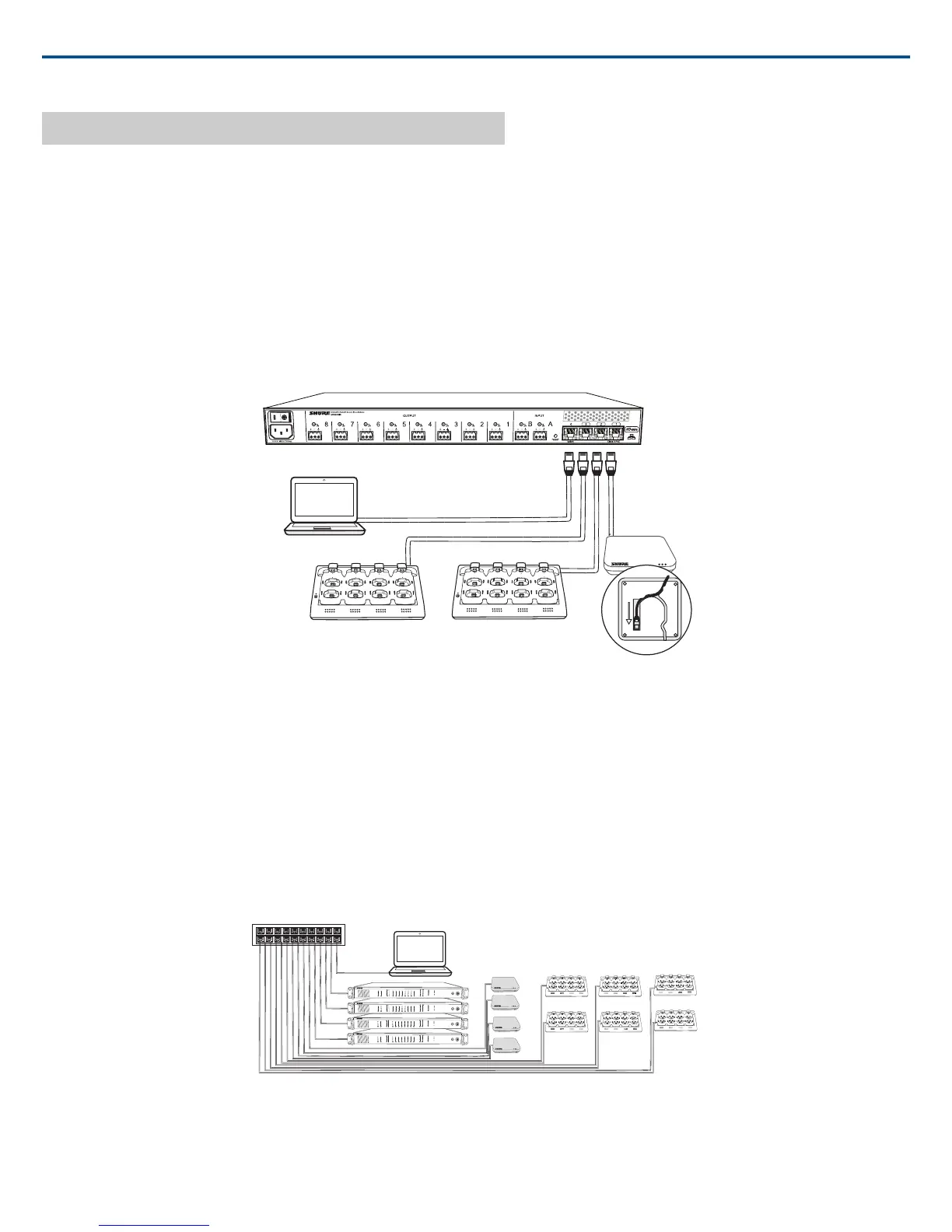
Multiple Group System (>1 Access Point)
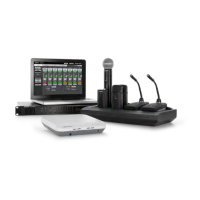
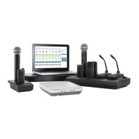
When an installation requires more than eight channels, additional MXW components can be connected to expand the system. A gigabit router is required to
connect all components to the same network. The following are several topologies for multiple group systems.
Use the Spectrum Scanner to ensure that there is sufficient RF availability for the installation.
Large Single-Room Installation
1. Power on the DHCP-enabled router.
2. Connect the router to a computer.
3. Connect each APT to a Power over Ethernet (PoE)-enabled port on the router. Use a PoE inserter if the router does not provide it.
4. Connect each ANI to the router.
5. Connect chargers to the ANI ports, or to the router.
7
8
6
5
1
2
3
4
7
8
6
5
1
2
3
4
7
8
6
5
1
2
3
4
7
8
6
5
1
2
3
4
7
8
6
5
1
2
3
4
7
8
6
5
1
2
3
4
lockout
power
ethernet
network audio
push to solo | hold to mute
-9
-18
-24
-36
-48
-60
0
-9
-12
-18
-24
0
aux
mic
adjust
line
sig/clip
mute
INPUT
A
sig/clip
mute
OUTPUT
HEADPHONE
Audio Network Interface
MICROFLEX WIRELESS
B
1
2
3
4
5
6
7
8
line
aux
lockout
power
ethernet
network audio
push to solo | hold to mute
-9
-18
-24
-36
-48
-60
0
-9
-12
-18
-24
0
aux
mic
adjust
line
sig/clip
mute
INPUT
A
sig/clip
mute
OUTPUT
HEADPHONE
Audio Network Interface
MICROFLEX WIRELESS
B
1
2
3
4
5
6
7
8
line
aux
lockout
power
ethernet
network audio
push to solo | hold to mute
-9
-18
-24
-36
-48
-60
0
-9
-12
-18
-24
0
aux
mic
adjust
line
sig/clip
mute
INPUT
A
sig/clip
mute
OUTPUT
HEADPHONE
Audio Network Interface
MICROFLEX WIRELESS
B
1
2
3
4
5
6
7
8
line
aux
lockout
power
ethernet
network audio
push to solo | hold to mute
-9
-18
-24
-36
-48
-60
0
-9
-12
-18
-24
0
aux
mic
adjust
line
sig/clip
mute
INPUT
A
sig/clip
mute
OUTPUT
HEADPHONE
Audio Network Interface
MICROFLEX WIRELESS
B
1
2
3
4
5
6
7
8
line
aux
lockout
power
ethernet
network audio
push to solo | hold to mute
-9
-18
-24
-36
-48
-60
0
-9
-12
-18
-24
0
aux
mic
adjust
line
sig/clip
mute
INPUT
A
sig/clip
mute
OUTPUT
HEADPHONE
Audio Network Interface
MICROFLEX WIRELESS
B
1
2
3
4
5
6
7
8
line
aux
7
8
6
5
1
2
3
4
lockout
power
ethernet
network audio
push to solo | hold to mute
-9
-18
-24
-36
-48
-60
0
-9
-12
-18
-24
0
aux
mic
adjust
line
sig/clip
mute
INPUT
A
sig/clip
mute
OUTPUT
HEADPHONE
Audio Network Interface
MICROFLEX WIRELESS
B
1
2
3
4
5
6
7
8
line
aux
7
8
6
5
1
2
3
4
lockout
power
ethernet
network audio
push to solo | hold to mute
-9
-18
-24
-36
-48
-60
0
-9
-12
-18
-24
0
aux
mic
adjust
line
sig/clip
mute
INPUT
A
sig/clip
mute
OUTPUT
HEADPHONE
Audio Network Interface
MICROFLEX WIRELESS
B
1
2
3
4
5
6
7
8
line
aux
7
8
6
5
1
2
3
4
lockout
power
ethernet
network audio
push to solo | hold to mute
-9
-18
-24
-36
-48
-60
0
-9
-12
-18
-24
0
aux
mic
adjust
line
sig/clip
mute
INPUT
A
sig/clip
mute
OUTPUT
HEADPHONE
Audio Network Interface
MICROFLEX WIRELESS
B
1
2
3
4
5
6
7
8
line
aux
Local System Star Setup
To minimize cabling, MXW components can use the Audio Network Interface as a local switch that connects to a shared network.
1. Power on the DHCP-enabled router.
Shure IncorporatedMXW
2017/05/1718/72