+
7
8
6
5
1
2
3
4
lockout
power
ethernet
network audio
push to solo | hold to mute
-9
-18
-24
-36
-48
-60
0
-9
-12
-18
-24
0
aux
mic
adjust
line
sig/clip
mute
INPUT
A
sig/clip
mute
OUTPUT
HEADPHONE
Audio Network Interface
MICROFLEX WIRELESS
B
1
2
3
4
5
6
7
8
line
aux
push to solo | hold to mute
sig/clip
mute
INPUT
line
aux
6
7
8
9
10
11
12
1
2
3
4
5
6
7
8
9
10
11
12
1
2
3
4
5
5
7
8
6
5
1
2
3
4
i
i
i i
i
i
i
i
i
i i
i
i
i
i
i
i
i i
i
i
i
i
i
i i
i
i
i
i
i
i
i i
i
i
i
i
i
i i
i
i
i
i
i
i
i i
i
i
i
i
i
i i
i
i
i
i
lockout
power
ethernet
network audio
push to solo | hold to mute
-9
-18
-24
-36
-48
-60
0
-9
-12
-18
-24
0
aux
mic
adjust
line
HEADPHONE
MICROFLEX WIRELESS
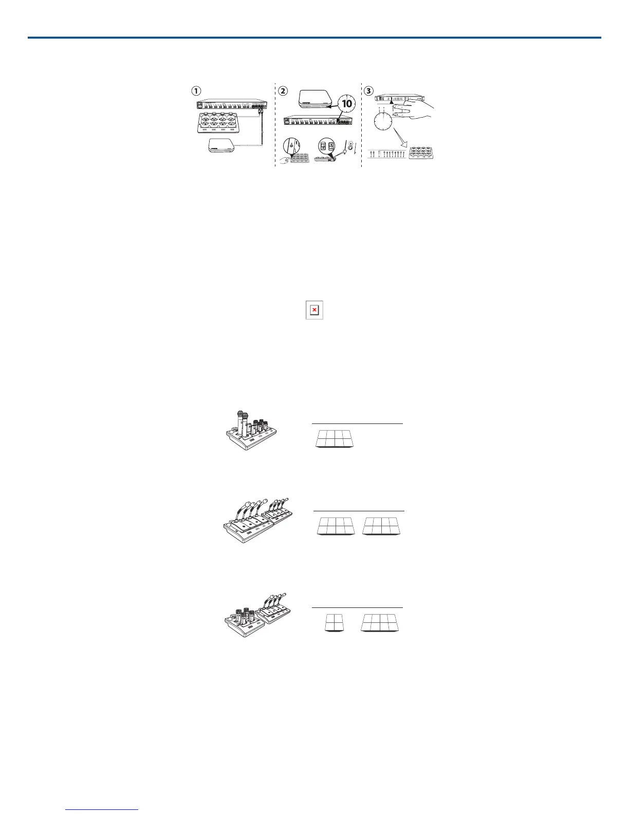
1. Connect one APT, one NCS and one ANI to the network. The network must only contain one of each device.
2. Perform a factory reset on the devices (see the Factory Default section).
3. On the front panel of the ANI, press both input level selection buttons at the same time and hold for five seconds. The Channel Select LEDs will illuminate
green and the audio meter will flash to indicate that the association is successful.
Channel Routing between Devices
Channels are routed when charging stations and output devices are selected to fill the APT group (2-, 4-, or 8-channels). Once the devices are selected for the
group, the channels are mapped between the charging slots, audio outputs and the wireless receiver.
Group selections are made from the Configuration tab of the control interface.
Group Selections Determine Routing
Each group has two selections available for charging stations and audio output devices. The selections determine the channel routing in the group.
Charging Station Examples
8-Channel Group
21
3 4
NCS A
NCS A
NCS A
NCS A NCS B
NCS B
NCS B
NCS B Out A Out B
Out A Out B
Out A Out B
2
1
1 2 3 4 5 6 7 8
1 2 3 4 5 6 7 8
2 3 4
x x x x
1
2 3 4
x x x x
1
6 7 8
x x x x
5
6 7 8
x x x x
5
1 2 3 4 x x x x
NCS A NCS B
AUX IN
MASTER
lockout
power
ethernet
network audio
automix link
dual mixer
LIM
A
B
-9
-18
-24
-36
-48
-60
0
gain
limiter
L+R SUM
gain
low cut
hi shelf
meter
push to solo | hold to mute
1 2 3 4 5 6 7 8
A B
HEADPHONE
lockout
power
ethernet
network audio
push to solo | hold to mute
-9
-18
-24
-36
-48
-60
0
-9
-12
-18
-24
0
aux
mic
adjust
line
sig/clip
mute
INPUT
A
sig/clip
mute
OUTPUT
HEADPHONE
Audio Network Interface
MICROFLEX WIRELESS
B
1
2
3
4
5
6
7
8
line
aux
lockout
power
ethernet
network audio
push to solo | hold to mute
-9
-18
-24
-36
-48
-60
0
-9
-12
-18
-24
0
aux
mic
adjust
line
sig/clip
mute
INPUT
A
sig/clip
mute
OUTPUT
HEADPHONE
Audio Network Interface
MICROFLEX WIRELESS
1
2
3
4
line
aux
lockout
power
ethernet
network audio
push to solo | hold to mute
-9
-18
-24
-36
-48
-60
0
-9
-12
-18
-24
0
aux
mic
adjust
line
sig/clip
mute
INPUT
A
sig/clip
mute
OUTPUT
HEADPHONE
Audio Network Interface
MICROFLEX WIRELESS
1
2
3
4
line
aux
x
x
Boundary, Handheld or Bodypack Microphones
Only one 8-channel charger is needed to fill the group with these types of microphones.
NCS B Out A Out B
Out A Out B
Out A Out B
2 3 4
5 6 7 8
1
2
1
1 2 3 4 5 6 7 8
1 2 3 4 5 6 7 8
6 7 8
x x x x
5
1 2 3 4 x x x x
NCS A NCS B
AUX IN
MASTER
lockout
power
ethernet
network audio
automix link
dual mixer
LIM
A
B
-9
-18
-24
-36
-48
-60
0
gain
limiter
L+R SUM
gain
low cut
hi shelf
meter
push to solo | hold to mute
1 2 3 4 5 6 7 8
A B
HEADPHONE
lockout
power
ethernet
network audio
push to solo | hold to mute
-9
-18
-24
-36
-48
-60
0
-9
-12
-18
-24
0
aux
mic
adjust
line
sig/clip
mute
INPUT
A
sig/clip
mute
OUTPUT
HEADPHONE
Audio Network Interface
MICROFLEX WIRELESS
B
1
2
3
4
5
6
7
8
line
aux
lockout
power
ethernet
network audio
push to solo | hold to mute
-9
-18
-24
-36
-48
-60
0
-9
-12
-18
-24
0
aux
mic
adjust
line
sig/clip
mute
INPUT
A
sig/clip
mute
OUTPUT
HEADPHONE
Audio Network Interface
MICROFLEX WIRELESS
1
2
3
4
line
aux
lockout
power
ethernet
network audio
push to solo | hold to mute
-9
-18
-24
-36
-48
-60
0
-9
-12
-18
-24
0
aux
mic
adjust
line
sig/clip
mute
INPUT
A
sig/clip
mute
OUTPUT
HEADPHONE
Audio Network Interface
MICROFLEX WIRELESS
1
2
3
4
line
aux
x
x
x
x
x
Gooseneck Microphones
This setup is used to fill an 8-channel group with gooseneck microphones. Channels are rerouted when an additional charger is added to the group. (The
gooseneck base is larger and covers two charger slots.)
21
3 4
NCS A
NCS A
NCS A
NCS A NCS B
NCS B
NCS B
NCS B Out A Out B
Out A Out B
Out A Out B
2 3 4
5 6 7 8
1
2
1
1 2 3 4 5 6 7 8
1 2 3 4 5 6 7 8
2 3 4
x x x x
1
2 3 4
x x x x
1
6 7 8
x x x x
5
6 7 8
x x x x
5
1 2 3 4 x x x x
NCS A NCS B
AUX IN
MASTER
lockout
power
ethernet
network audio
automix link
dual mixer
LIM
A
B
-9
-18
-24
-36
-48
-60
0
gain
limiter
L+R SUM
gain
low cut
hi shelf
meter
push to solo | hold to mute
1 2 3 4 5 6 7 8
A B
HEADPHONE
lockout
power
ethernet
network audio
push to solo | hold to mute
-9
-18
-24
-36
-48
-60
0
-9
-12
-18
-24
0
aux
mic
adjust
line
sig/clip
mute
INPUT
A
sig/clip
mute
OUTPUT
HEADPHONE
Audio Network Interface
MICROFLEX WIRELESS
B
1
2
3
4
5
6
7
8
line
aux
lockout
power
ethernet
network audio
push to solo | hold to mute
-9
-18
-24
-36
-48
-60
0
-9
-12
-18
-24
0
aux
mic
adjust
line
sig/clip
mute
INPUT
A
sig/clip
mute
OUTPUT
HEADPHONE
Audio Network Interface
MICROFLEX WIRELESS
1
2
3
4
line
aux
lockout
power
ethernet
network audio
push to solo | hold to mute
-9
-18
-24
-36
-48
-60
0
-9
-12
-18
-24
0
aux
mic
adjust
line
sig/clip
mute
INPUT
A
sig/clip
mute
OUTPUT
HEADPHONE
Audio Network Interface
MICROFLEX WIRELESS
1
2
3
4
line
aux
x
x
x
x
x
Mixture of Gooseneck and Boundary Microphones
When 4-channel and 8-channel chargers are selected, group channels five through eight are automatically routed to the back row of the 8-channel charger.
Shure IncorporatedMXW
2017/05/1732/72