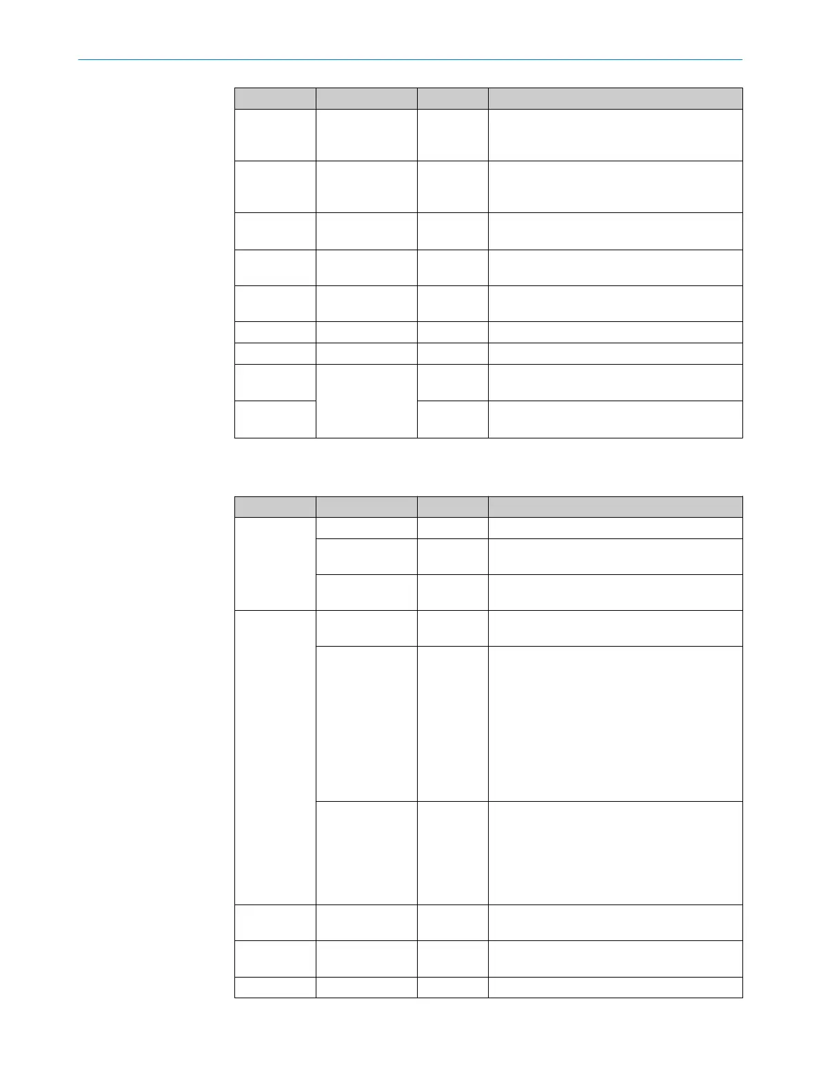
Color Display LED Status
Magenta – Flashing Device with heating (CLV61x-DxxxxF0):
Device not yet ready for operation, still in the
warm-up phase.
Blue Ready Steadily lit After switching on or after successful firmware
download:
Self-test successful, device ready for operation
– – Goes out After switching on:
Parameter download to / upload from device
Green G Read Lights up
briefly
Reading successful (Good Read)
Red N Read Lights up
briefly
Reading unsuccessful (No Read)
Red HW Err Steadily lit Hardware error
Light blue UserDef1 Off UserDef1 (reserved)
Red
Blue
Further indicators Alternating
flashing
Firmware download
Red Steadily lit Firmware download:
Error: Completion not successful
Network LEDs
Table 10: Display behavior of the sensor LEDs
Display LED Color Status
SF
1)
Off – Device without internal error
Steadily lit Red The device activates the internal PROFINET
module
Flashing Red Using the PROFINET TOOL, a blink request was
sent to the device for device identification
BF
2)
Off – Data exchange between device and PROFINET
controller via PROFINET possible
Steadily lit Red No connection between device and PROFINET
controller.
Possible causes:
•
Bus not connected electrically
•
PROFINET controller not available or
switched off
•
Incorrect PROFINET name
•
Wrong GSD file used
•
Wrong GSD module selected
Flashes cyclically Red Flash frequency 0.5 Hz.
Possible causes:
•
Configuration error in the PROFINET con‐
troller (e.g. ID wrong), no data exchange
•
Error in the PROFINET controller when con‐
figuring with modules, no data exchange
P1 LNK/ACT Off – Device not connected to any active network; no
data traffic possible
P1 LNK Steadily lit Green Device connected to active network, e.g. with
an Ethernet switch (switched-on)
P1 ACT Flickering Orange Device is sending or receiving data
8 OPERATION
46
O P E R A T I N G I N S T R U C T I O N S | CLV61x DualPort (PROFINET) 8017842/ZOK7/2019-02-01 | SICK
Subject to change without notice
 Loading...


