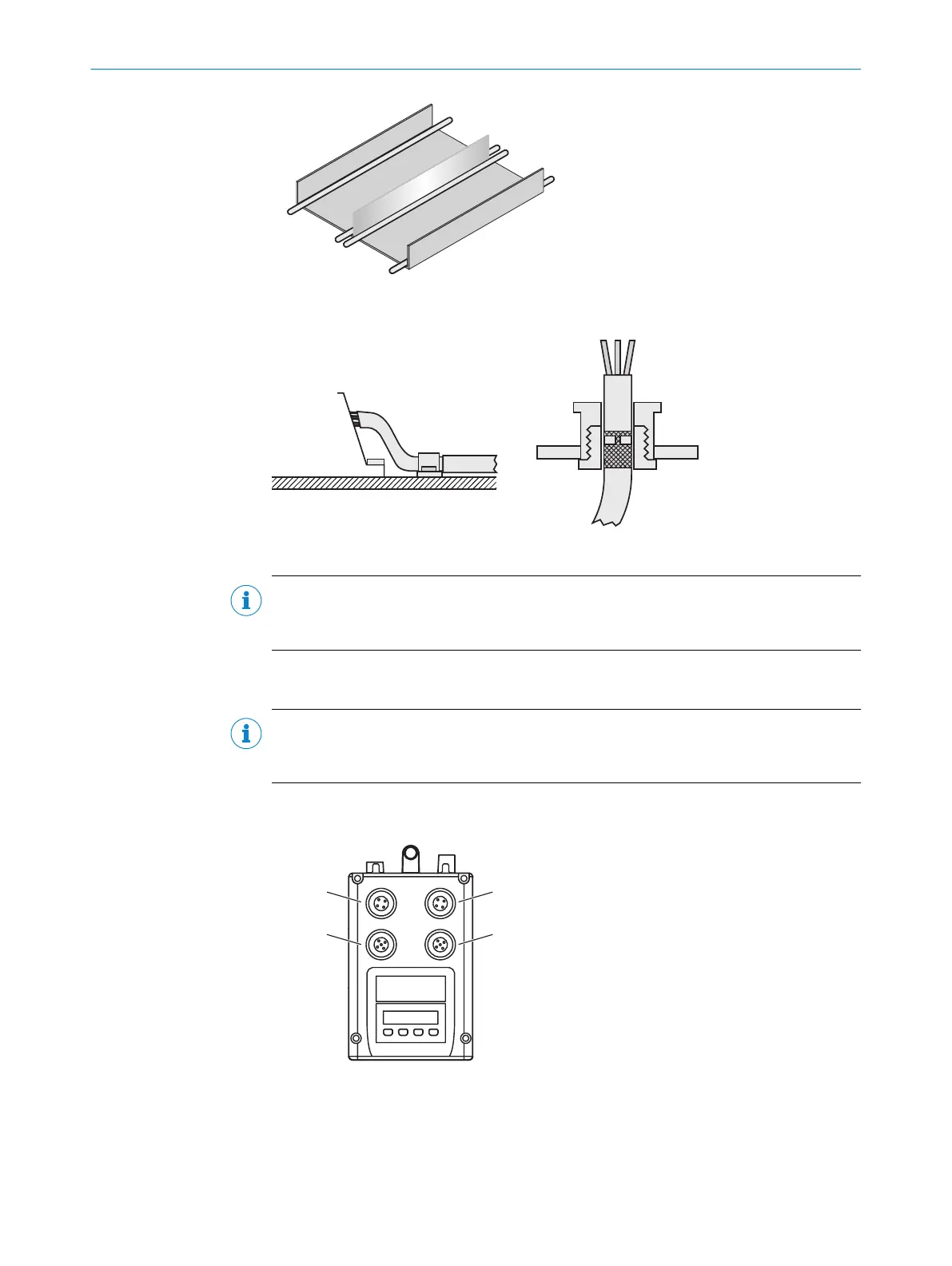
Figure 18: Alternative laying – Separate cables with metallic separators
Figure 19: Shield connection in plastic housings
NOTE
Use an appropriate earthing method to prevent equipotential bonding currents flowing
through the cable shield.
6.3 Connecting the device electrically
NOTE
The connection diagram, and information on inputs and outputs can be found on the
type label on the device.
1. Ensure the voltage supply is not connected.
2. Connect the device according to the connection diagram.
Figure 20: Position of electrical connections
1
Supply voltage (male connector M12, 4-pin, A-coded)
2
Ethernet (female connector M12, 4-pin, D-coded)
3
CANopen output (female connector M12, 5-pin, A-coded)
4
CANopen input (male connector M12, 5-pin, A-coded)
6 ELECTRICAL INSTALLATION
32
O P E R A T I N G I N S T R U C T I O N S | DL100 Pro CANopen 8015418/19HA/2022-12-15 | SICK
Subject to change without notice