For example, if there are 20 nodes with node IDs 1 to 20, the TPDO5 can be mapped
into the still free CAN ID range of TPDO1.
For this purpose, the node ID of the DL100 Pro must be set to 21 (15h) and the COB ID
of the TPDO5 must be set to 195h (180h+15h=195h).
Dynamic mapping is used to map objects into a TPDO. By default, TPDOs 5 and 6 are
empty and can accept objects. A TPDO can hold a maximum of 8data bytes.
TPDO1 and TPDO2 are already mapped by default according to device profile CiA 406.
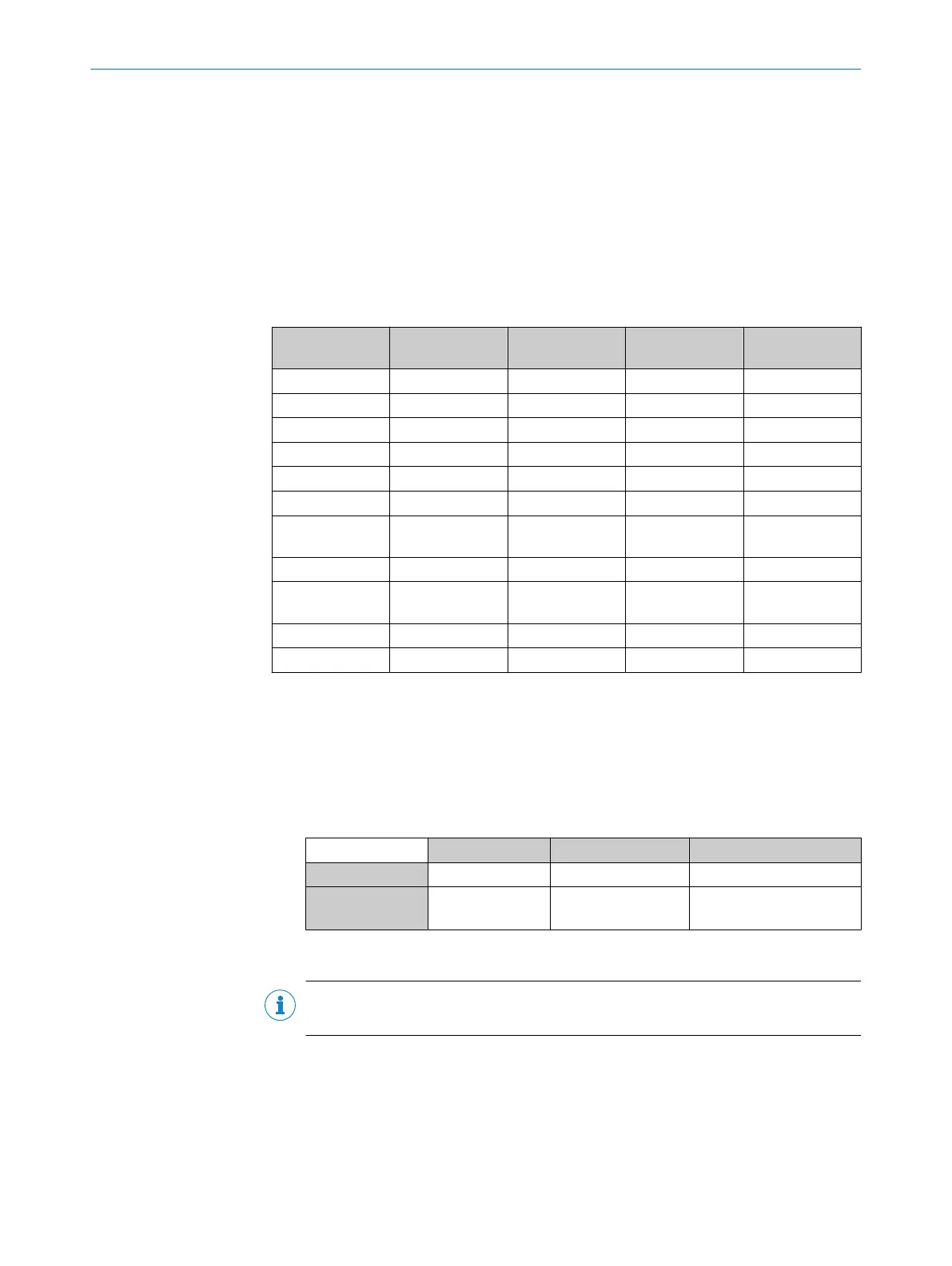
The following objects can be mapped:
Table 45: Mapping objects
Index Subindex Name Data type Resulting map‐
ping entry
2000h 0h Distance Integer32 0x2000 00 20
2001h 0h Velocity Integer32 0x2001 00 20
2002h 0h Time stamp Unsigned32 0x2002 00 20
2003h 0h Level Integer16 0x2003 00 10
2004h 0h Warnings Unsigned8 0x2004 00 08
2005h 0h Errors Unsigned8 0x2005 00 08
4004h 0h Device Tempera‐
ture
Integer8 0x4004 00 08
6004h 0h Position Value Unsigned32 0x6004 00 20
6030h 1h Speed Value
Channel 1
Integer16 0x6030 01 10
6503h 0h Alarms Unsigned16 0x6503 00 10
6505h 0h Warnings Unsigned16 0x6505 00 10
Procedure for dynamic mapping using TPDO5 as an example
1. Deactivate TPDO (e.g. object 1804h for TPDO5 Communication Parameter): Set bit
31 of COB ID to 1.
2. Set number of mapping entries in subindex 0 (e.g. object 1A04h for TPDO5 map‐
ping parameters) to 0. This invalidates all mapping entries from now on.
3. Set desired mapping entries in subindex 1 to 8 of object 1A04h (for TPDO5), e.g.
0x60040020. A mapping entry is composed as follows:
Byte 3 ... 2 Byte 1 Byte 0
Meaning Index Subindex Number of bits
Example 6004h
(Position Value)
00h 32d = 20h
4. Set number of mapping entries. For example, if two mapping entries were set
valid, the number of mapping entries in subindex 0 must be set to 2.
NOTE
A TPDO can hold a maximum of 8data bytes of user data.
10.4.7 Emergency messages (EMCY messages)
“Emergency” type messages are used to signal errors of a device. In the emergency
telegram, a code is transmitted that uniquely identifies the error (defined in the CiA301
communication profile as well as in the respective CiA40x device profiles).
CANOPEN INTERFACE 10
8015418/19HA/2022-12-15 | SICK O P E R A T I N G I N S T R U C T I O N S | DL100 Pro CANopen
85
Subject to change without notice