6.4 Connection diagrams
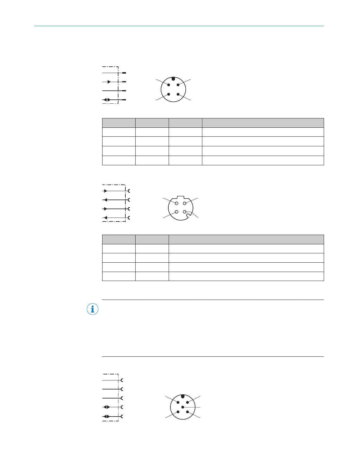
6.4.1 MF1, MF2 supply voltage connection diagram
L+
MF2
M
MF1
1
2
4
wht
blu
brn
blk
3
Figure 21: MF1, MF2 supply voltage connection diagram
Contact Identifier Wire color Description
1 L+ Brown Supply voltage: +18 ... +30V DC
2 MF2 White Multifunctional output MF2, B-type
3 M Blue Supply voltage: 0 V
4 MF1 Black Multifunctional input and output MF1, B-type
6.4.2 Ethernet connection diagram
Table 7: Ethernet port connection diagram
Contact Marking Description
1 Tx+ Send data signal +
2 Rx+ Receive data signal +
3 Tx– Send data signal –
4 Rx– Receive data signal –
6.4.3 CANopen connection diagram
NOTE
The voltage supply to the device is usually provided via male connector 1 (see "MF1,
MF2 supply voltage connection diagram", page 33). For the device variant without
integrated heating (DL100-xxAxxx09), an optionally available bus voltage V+ / V- (pin
2/pin 3 on male connector 3 or male connector 4) can be used as an alternative.
When connecting the voltage supply both via male connector 1 and via male connec‐
tors 3/4, supply via male connector 1 is used internally in the device.
CANopen input connection diagram
FE (shield)
V+
CAN_H
1
2
4
red
blk
wht
blu
V–
3
CAN_L
5
ELECTRICAL INSTALLATION 6
8015418/19HA/2022-12-15 | SICK O P E R A T I N G I N S T R U C T I O N S | DL100 Pro CANopen
33
Subject to change without notice