Table 8: CANopen input connection diagram, male connector M12, 5-pin, A-coded
Contact Signs Wire color Description
1 FE Shielding Cable lug
2 V+ Red Supply voltage: +18 … +30V DC
3 V- Black Supply voltage: 0 V
4 CAN_H White CAN bus signal
5 CAN_L Blue CAN bus signal
Thread FE Shielding Cable lug (housing)
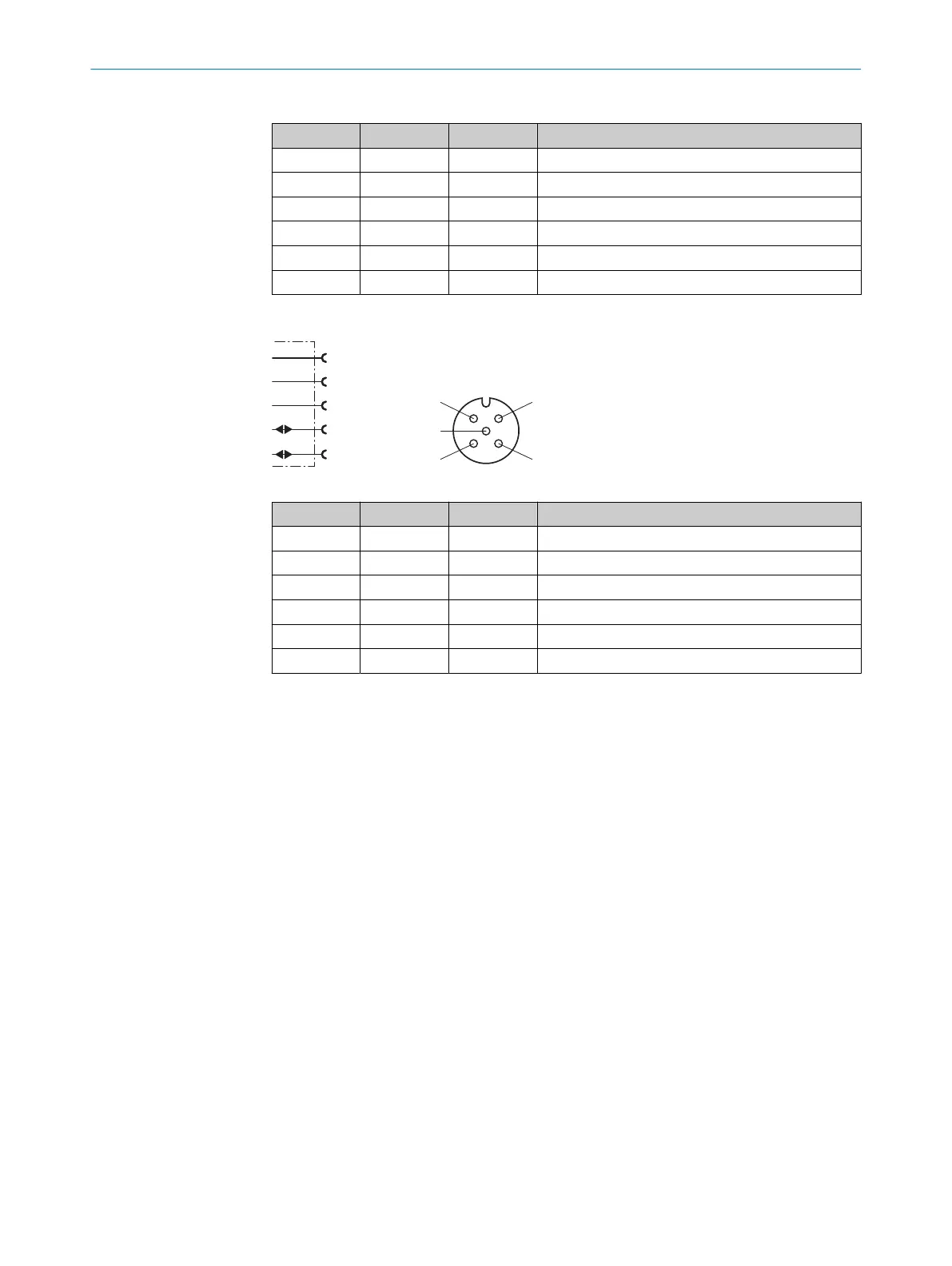
CANopen output connection diagram
FE (shield)
V+
CAN_H
1
2
4
red
blk
wht
blu
V–
3
CAN_L
5
Table 9: CANopen output connection diagram, male connector M12, 5-pin, A coded
Contact Signs Wire color Description
1 FE Shielding Cable lug
2 V+ Red Supply voltage: +18 … +30V DC
3 V- Black Supply voltage: 0 V
4 CAN_H White CAN bus signal
5 CAN_L Blue CAN bus signal
Thread FE Shielding Cable lug (housing)
6 ELECTRICAL INSTALLATION
34
O P E R A T I N G I N S T R U C T I O N S | DL100 Pro CANopen 8015418/19HA/2022-12-15 | SICK
Subject to change without notice