DE
RE\
VCC
R
D
A
B
VSS
C1
C2
R1
R2
7..12 VDC
DATA+
DATA-
PWR+
PWR-
DSL
EN
DSL
IN
DSL
OUT
U2
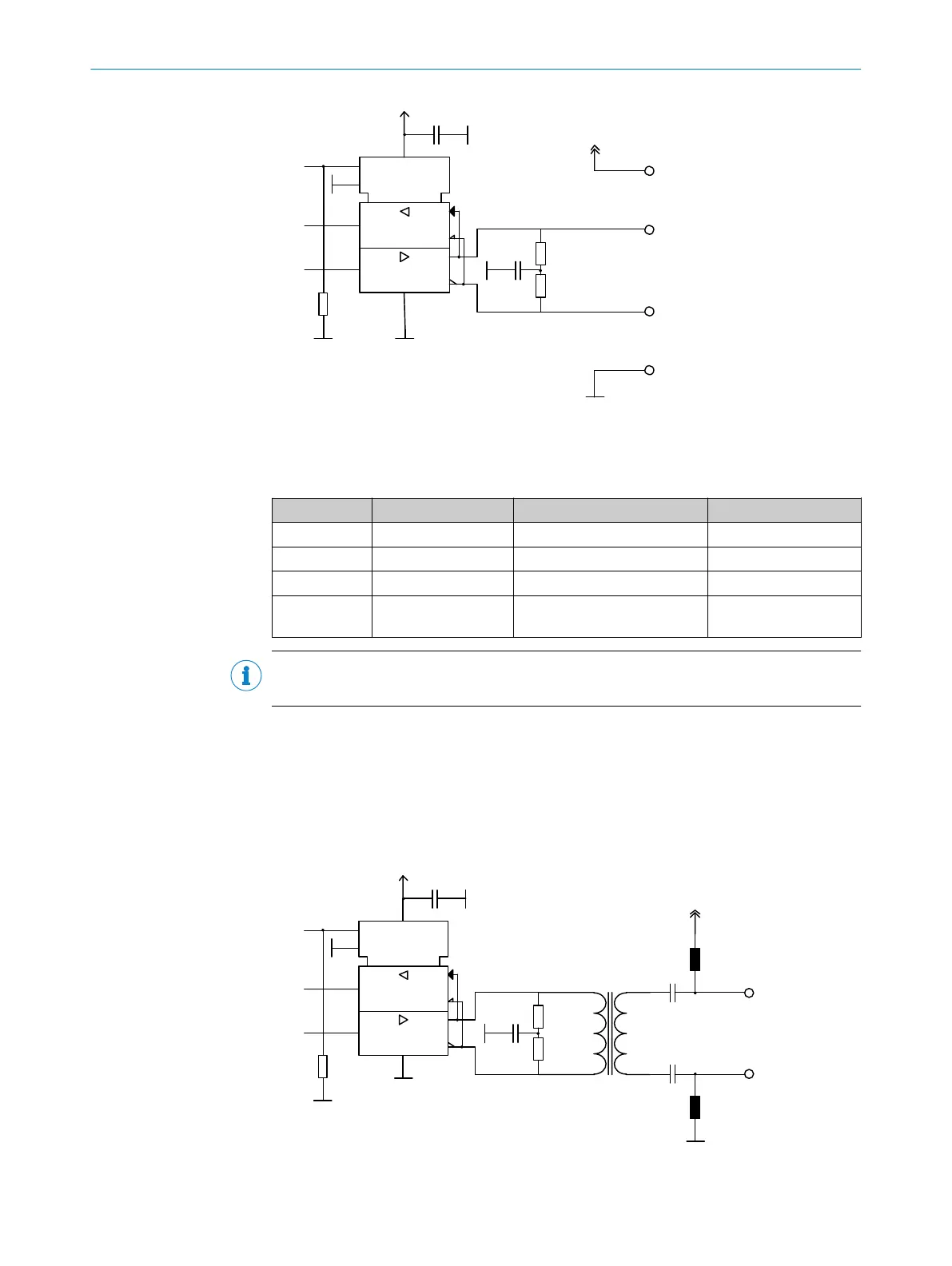
Figure 5: Interface circuit with separate encoder cable
Recommended components for the interface circuit are set out in table 4.
Table 4: Components for the interface circuit with separate encoder cable
Component Part Manufacturer
C1 Ceramic capacitor 100 nF
C2 Ceramic capacitor 2.2 µF, 16 V
R1, R2 Resistors 56R
U2 RS485 transceiver SN65LBC176A
SN75LBC176A
Texas Instruments
Texas Instruments
NOTE
The use of four core cable is no longer recommended for the motor cable.
4.1.2 Integrated cable - two core cable
For a connection via a two core cable integrated in the motor cable, (see chapter 4.3),
the data cables must be provided with a transformer to raise the common mode rejec‐
tion ratio. To feed the supply voltage into the data cables choke coils are also required.
In connection with the associated table, figure 6 below gives the specification of the
interface circuit.
DE
RE\
VCC
R
D
A
B
VSS
U2
C1
C2
R1
R2
TR1
C3
C4
7..12 VDC
L1
L2
DSL+
DSL-
DSL
EN
DSL
IN
DSL
OUT
Figure 6: Interface circuit with two core cable (integrated in cable)
4 HARDWARE INSTALLATION
16
T E C H N I C A L I N F O R M A T I O N | HIPERFACE DSL
®
8017595/ZTW6/2018-01-15 | SICK
Subject to change without notice
 Loading...


