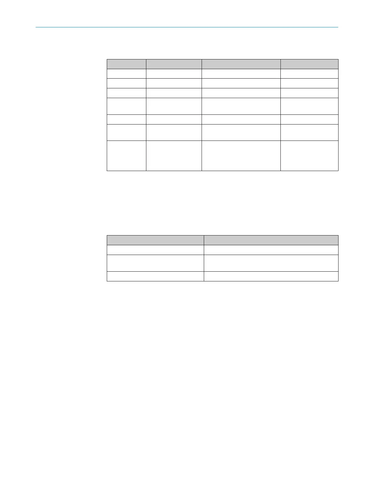
Recommended components for the interface circuit are set out in table 5.
Table 5: Components of the interface circuit with two core cable (integrated in cable)
Component Part Manufacturer
C1 Ceramic capacitor 100 nF
C2 Ceramic capacitor 2.2 µF, 16 V
C3, C4 Ceramic capacitor 470 nF, 50 V
L1, L2 Choke coils 744043101, 100 µH
ELL6SH101M, 100 µH
Würth Elektronik
Panasonic
R1, R2 Resistors 56R
U2 RS485 transceiver SN65LBC176A
SN75LBC176A
Texas Instruments
Texas Instruments
TR1 Transformer PE-68386NL
78602/1C
B78304B1030A003
78602/1C
Pulse Engineering
Murata
Epcos
Epcos
4.1.3 Motor feedback voltage supply
Motor feedback systems with HIPERFACE DSL
®
have been developed for operation with
a supply voltage of 7 to 12 V. The voltage supply is measured at the encoder plug con‐
nector.
table 6 below describes the specification for the power supply.
Table 6: Voltage supply
Parameter Value
Switch-on voltage ramp Max. 180 ms from 0 to 7 V
Inrush current Max. 3.5 A (0 to100 µs)
Max. 1 A (100 µs to 400 µs)
Operating current Max. 250 mA at 7 V
4.1.4 Interface circuit design recommendations
figure 5 and figure 6 show the two different interface circuits depending on the chosen
system configuration. The following recommendations help in attaining a system design
optimized for transmission robustness.
•
During PCB design a good RF isolation for the interface circuit shall be achieved
against the motor power circuit.
•
The two sides of the transformer TR1 have to be well separated from each other to
avoid crosstalk.
•
Inside the servo controller the DSL-signal lines shall be routed as short as possible
and with good symmetry in the differential part. To avoid or reduce signal distur‐
bances by EMC-noise it is recommended to place this circuit as close as possible
to the connection point of the DSL-lines.
•
During PCB layout design also assess and avoid potential EMC-noise coupling
from brake lines as well as the brake power supply circuit.
•
For the encoder power supply via L1/L2 a star connection to a very low impedance
point is important. Both inductances shall be well matched to each other to avoid
differential mode noise. Self-resonance frequency should be of at least 10 MHz. A
common mode filter between L1/L2 and the supply voltage can improve robust‐
ness.
•
The DSL-line impedance is matched balanced by 2 x 56 Ohm. C2 grounds remain‐
ing common mode noise after the transformer; RF parts shall be used or different
types paralleled to get low impedance on a broader frequency range. PCB design
HARDWARE INSTALLATION 4
8017595/ZTW6/2018-01-15 | SICK T E C H N I C A L I N F O R M A T I O N | HIPERFACE DSL
®
17
Subject to change without notice
 Loading...


