Signal name Type Function
dsl_out* Output DSL cable, output data
dsl_en* Output DSL cable transceiver, activation
spipipe_ss Input SensorHub SPI slave select
spipipe_clk Input Serial clock for SPI SensorHub
spipipe_miso Output SPI SensorHub, master output data/slave input
data
online_status_d Output (16) IP Core status information
hostd_a Input (7) Host interface address
hostd_di Input (8) Host interface data in
hostd_do Output (8) Host interface data out
hostd_r Input Host interface data read
hostd_w Input Host interface data write
hostd_f Input Host interface register freeze
* these signals must be assigned to physical pins of the FPGA.
4.2.2 SYNC signal
The HIPERFACE DSL
®
communication can be established in “SYNC mode” or “free run‐
ning mode”. In free running mode, the IP-Core will use the fastest possible transmis‐
sion timing and this input should be low (0). Please note that the IP-Core is not bound
to any timing of the frequency inverter in this mode.
In SYNC mode the frequency inverter clock must be supplied to this input/pin. Please
refer to table 8 for the signal specification. This signal triggers position sampling of the
DSL encoder. The polarity of the edge can be programmed using the SPOL bit in the
SYS_CTRL register.
As the frame cycle time must always be within a limited range, a divider for the SYNC
frequency has to be chosen accordingly. The divider value needs to be written to the
SYNC_CTRL register.
NOTE
In case of the SYNC frequency changing, the IP-Core will synchronize automatically. Dur‐
ing this synchronization the former sampling frequency is used. Please note that this
synchronization takes a few SYNC periods.
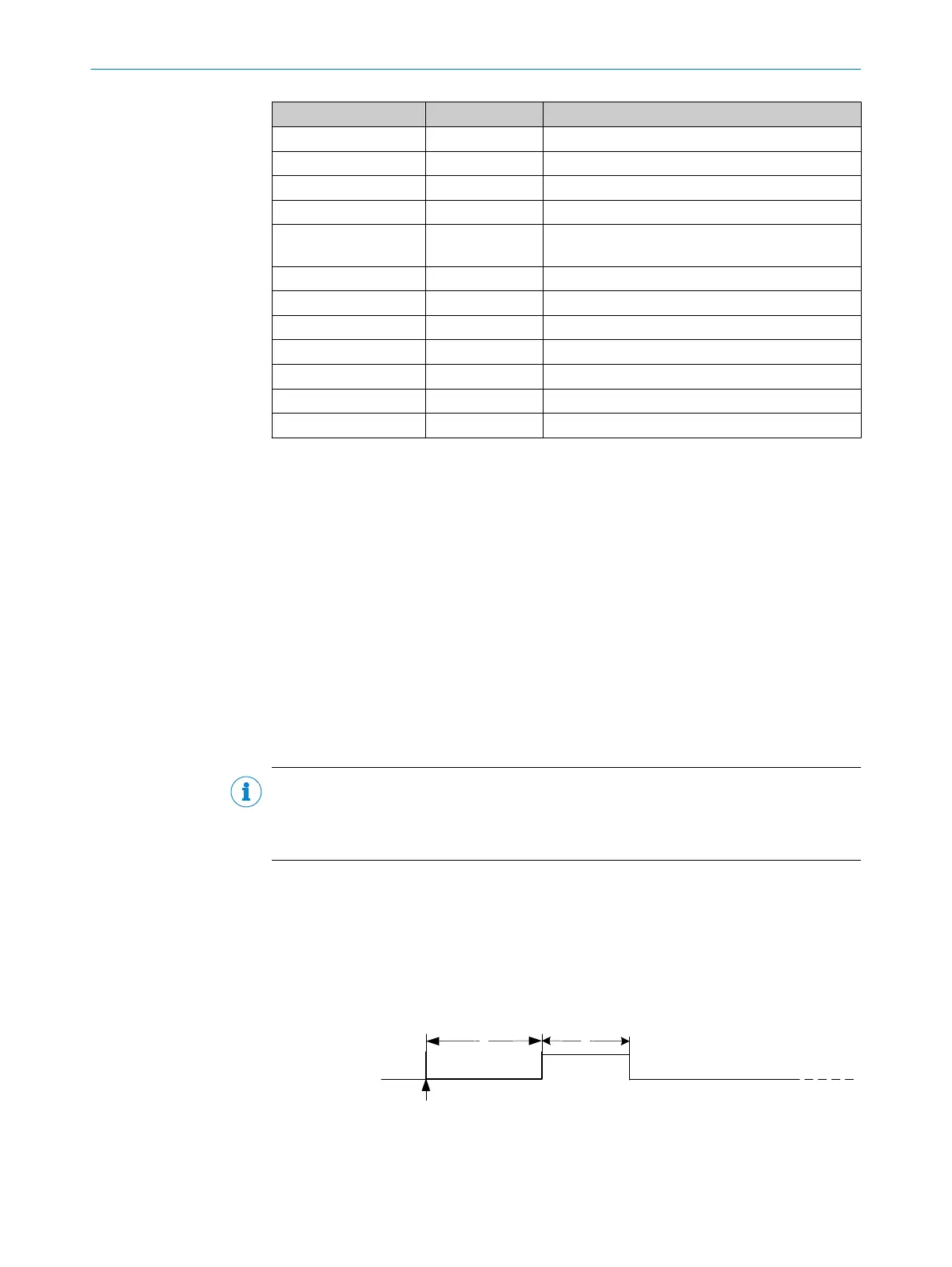
4.2.3 Reset signal
rst is the reset input (high active) of the DSL Master IP Core.
After start-up (switching on) of the frequency inverter, a reset procedure is mandatory to
return the DSL Master IP Core to its initialization condition.
The reset procedure is established by the parameters listed in table 8 and quoted in
figure 8.
Figure 8: Reset procedure
4 HARDWARE INSTALLATION
20
T E C H N I C A L I N F O R M A T I O N | HIPERFACE DSL
®
8017595/ZTW6/2018-01-15 | SICK
Subject to change without notice
 Loading...


