Operating instructions Chapter 4
Flexi Classic
8011509/YPP0/2015-10-26 © SICK AG • Industrial Safety Systems • Germany • All rights reserved 77
Subject to change without notice
Special applications and
functions
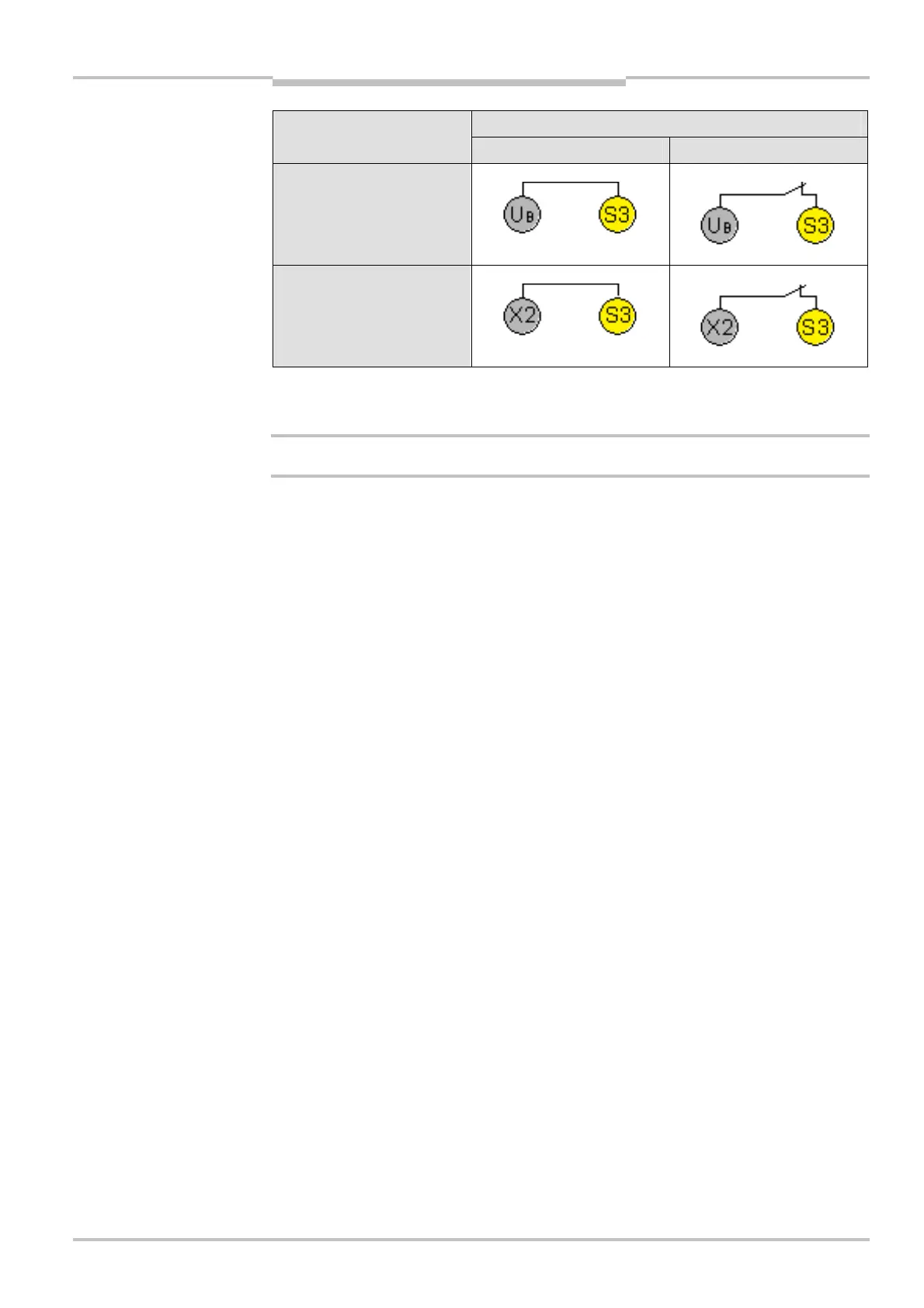
S3Connecting
Without EDM With EDM
Without retriggering
With retriggering
• S1 and S3 must always be connected.
• S2 must be connected depending on the program.
All later changes at the connection of S1, S2 and S3 cause a lock-out (ERR).
• During the configuration phase (when the voltage is activated) of the manual reset with
the reset button, the corresponding S-input must be open or be connected to a high-
resistance output, for example of a PLC (high or low potential causes an incorrect
configuration).
• In order to monitor external contactors that may be connected to the safe outputs Q1 to
Q4, the N/C contacts of the respective contactors or output extensions have to be con-
nected in series with the corresponding control inputs.
of S3
Notes
WARNING
 Loading...

