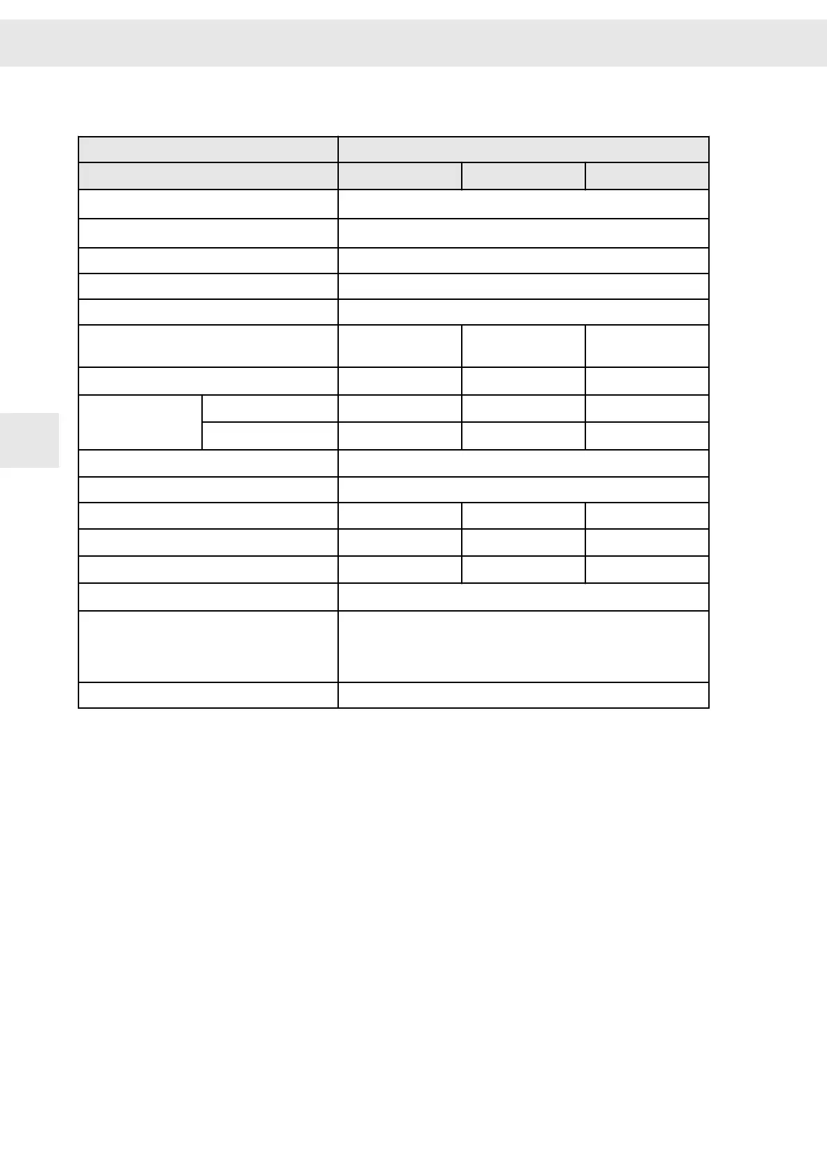
6.4 Technical Data
Device variant 0362170DB
Parameterized supply voltage
(1)
24 V
DC
48 V
DC
80 V
DC
Continuous phase current of output stage (±3 %)
7 A
rms
(when mounted to cooling surface of the installation)
(2)
Peak phase current of output stage (±3 %)
10 A
rms
(when mounted to cooling surface of the installation)
(2)
Max. time for peak current 10 s
Max. output frequency 2000 Hz
Output frequency stability ≤ 0.2 %
Supply voltage
(3)
24 V
DC
(-10 %) to
24 V
DC
(+15 %)
24 V
DC
(-10 %) to
48 V
DC
(+15 %)
24 V
DC
(-10 %) to
80 V
DC
(+15 %)
Output voltage
16 V
AC
33 V
AC
55 V
AC
Output power
S
S
at I
rated
(7 A
rms
) 190 VA 390 VA 660 VA
S
at I
rated
(10 A
rms
) 270 VA 550 VA 940 VA
Logic supply
(4)
18 – 28 V
DC
(0.5 A)
Internal ballast resistor 22 Ω / 50 W
Maximum braking power 50 W 200 W for 5 s 450 W for 2 s
Ballast threshold 35 V
DC
65 V
DC
100 V
DC
Overvoltage threshold 40 V
DC
70 V
DC
110 V
DC
Undervoltage threshold 15 V
DC
Ambient temperature range 5 °C to 50 °C at a maximum relative humidity of 85 % (without moisture
condensation)
100 % rated current up to max. 40 °C. At higher temperatures the power
must be reduced by 1.5 % per 1 °C.
IP Code
IP00
(1)
Adjustable via software
drivemaster2
: from device version 4.100 and software version 1.14.100 onwards
For SD2B / SD2B plus with a device version < 4.100 the column 80 V
DC
applies. Device version 4.0xx can
be reconfigured to reach version 4.100, see “TIE_SD2B_AdjustableSupplyVoltage.pdf”.
(2)
Minimum size of cooling surface: 6 dm² (natural convection)
(3)
Admissible voltage ripple: max. 10 %
The supply voltage is protected by a fuse on the device: 10 A medium slow (5 × 20 mm)
(4)
The logic voltage is necessary to maintain the error messages. It is protected by an electronic fuse on the
device.
Device variant SD2B
W
30 Drive Amplifier SD2B / SD2B plus - Hardware Description
6