Current range
The current range specifies the maximum admissible currents. Distinction is made
between peak and rated current:
▶ The peak current is only admissible for a short time (mostly 1 second) and
depends on the used diodes and their number.
▶ The rated current can be provided continuously by the power supply unit. Its value
depends on the cooling of the diodes, that means: the capacity of the used heat
sink and its ventilation.
Power
In practice, a maximum permanent power is specified for power supply units, since the
supply voltage is assumed to be constant. As the limitation in the power supply unit is
determined by the load carrying capacity of the diodes, the maximum permanent
power depends on the supply voltage and the type of supply.
Examples:
▶ Power supply 230 V
AC
, 2 phases, max. permanent current of the diodes 6 A
230 V
AC
× 2 × 6 A = 2.76 kW
▶ Power supply 400 V
AC
, 3 phases, max. permanent current of the diodes 6 A
400 V
AC
× 3 × 6 A = 7.20 kW
The maximum peak current depends on the type of diode used.
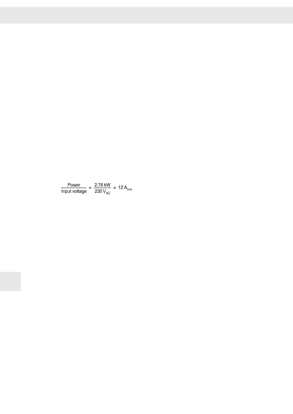
The protection is calculated as follows:
12.1.3 Motor
The motor is specified by the following details:
Peak current
The peak current defines the max. allowed motor current. The peak current is only
allowed for a short period of time (between 1 and 30 Sekunden) and depends on the
used magnetic material and the thickness of the windings. Normally, the motor manu‐
facturer defines the peak current applying during downtimes and during a rotating field.
Generally, the values given on the motor data sheet are RMS values. SIEB & MEYER
specifies currents as sine peak amplitudes.
The RMS values are calculated by dividing these values by the factor √2.
Rated current
The rated current can be applied permanently to the motor. The value depends on the
cooling of the motor, the windings and the max. allowed motor temperature. Normally,
the motor manufacturer defines the rated current applying during downtimes and
during a rotating field. Generally, the values given on the motor data sheet are RMS
values. SIEB & MEYER specifies currents as sine peak amplitudes.
The RMS values are calculated by dividing these values by the factor √2.
The current version of the software drivemaster2 allows switching between the RMS
value and the sine peak amplitude (see “Settings ÿ Program settings ÿ View”).
When switching the view, the existing values are automatically converted into the new
unit. The default setting is the RMS value.
Electric Performance Dimensioning
W
72 Drive Amplifier SD2B / SD2B plus - Hardware Description
12