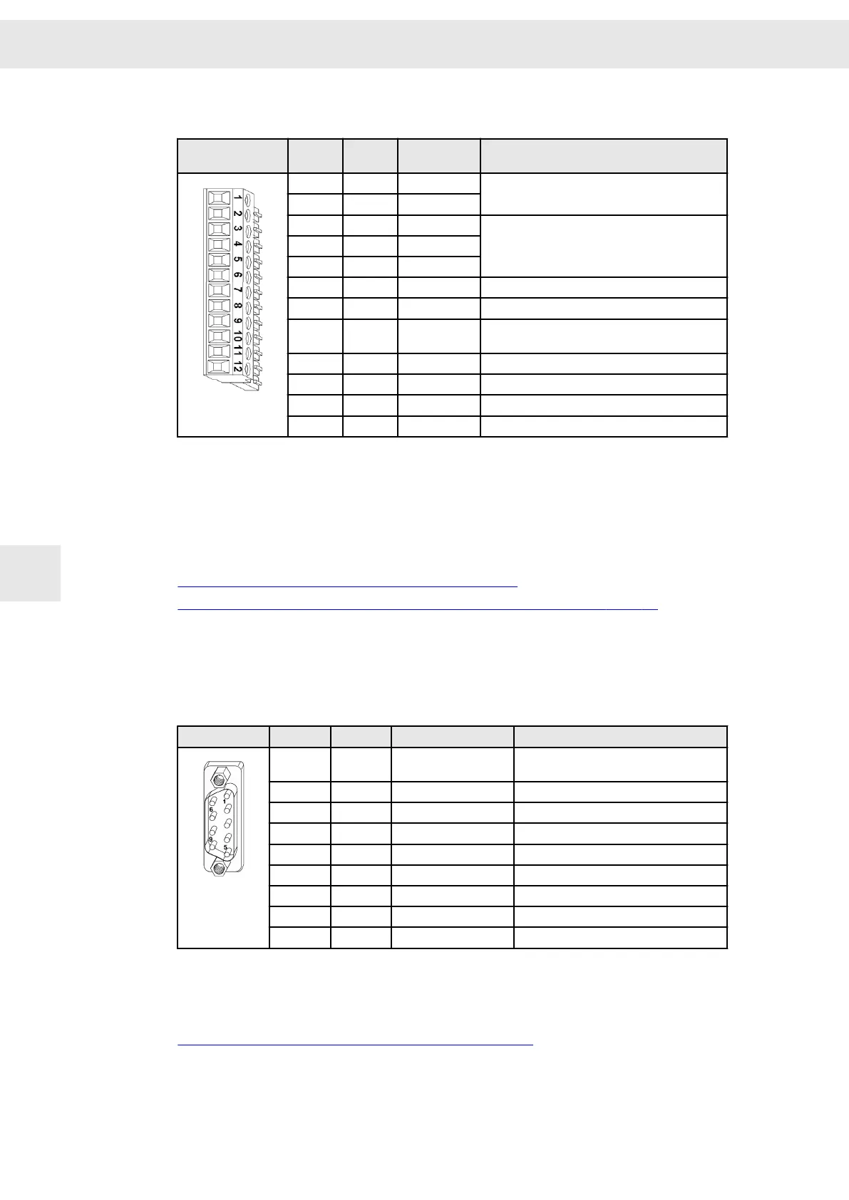
12-pole Mini-Combicon connector, suitable for mating connector MC 1,5/ 12-ST-3,81
(Phoenix)
Mating connector
X9
Pin I/O Name Meaning
1 I IN0
Digital 24 V
DC
input
2 I IN1
3 O OUT0
Digital output
(1)
▶ low-side driver: max. 500 mA, max. 40 V
▶ high-side driver: max. 100 mA
4
O OUT1
5 O OUT2
6 O VCC_10 10 V voltage supply for analog input
7 I/O GND Ground
8 I Temp Temperature sensor of the motor (against
GND)
9 I AIN0+ ±10 V analog input
10 I AIN0− Reference point of AIN0+ (pin 9)
11 I/O GND Ground
12 I/O GND Ground
(1)
You can set the desired type of the output driver in the software
drivemaster2
.
Specification of terminal connections
▶ Conductor cross-section solid/stranded: 0.14 to 1.5 mm²
▶ Tightening torque: 0.22 to 0.25 Nm
Related topics
Connection examples: "X9 – Inputs/Outputs", page 49
Connection example: "X9/X14 – Temperature Sensor of the Motor", page 50
8.7 X10 – COM1 / Operating Terminal
9-pole male submin D connector
X10
Pin I/O Name Meaning
1 O VCC 5.3 V (power supply for optional oper‐
ating terminal, short-circuit proof)
2 I RX Receive data
3 O TX Transmit data
4 I/O CAN_L CAN_L
5 I/O GND Ground
6 I RX2 Receive data 2
7 O TX2 Transmit data 2
8 I/O CAN_H CAN_H
9 I/O GND Ground
Stud bolt flange: max. tightening torque = 0.7 Nm
Related topics
Connection examples: "X10 – Bus Connection", page 51
Connector Pin Assignment
W
42 Drive Amplifier SD2B / SD2B plus - Hardware Description
8