Mating
connector
X14
Pin
I/O Name Meaning
B3 I A IN− Reference point for AIN+ (pin B4)
B4 I A IN+ Analog input
B5 I VCC10 10 V supply voltage
B6 I TEMP Motor temperature (to be connected towards
GND)
B7 I/O GND Ground
B8 I IN4 Digital input
B9 I IN3 Digital input
B10 I IN2 Digital input
B11 I IN1 Digital input
B12 I IN0 Digital input
(1)
The 24 V output is not suited to supply external safety circuits because an external voltage source is
necessary to comply with the applicable standards.
The power supply unit is only activated when SAFE A and SAFE B are
connected. If the safety function is not required, pin A5 and pin A6 must be
bridged to pin A4.
Specification of terminal connections
▶ Conductor cross-section solid/stranded: 0.2 to 1.5 mm²
▶ Connection method: spring-cage connection (handling: see page 39)
Related topics
Connection examples: "X14 – In/Out / STO", page 53
Connection example: "X9/X14 – Temperature Sensor of the Motor", page 50
Connection example: "X12/X14 – DC Power Supply Unit", page 53
Safety function STO: "Safety Circuit / Restart Lock (STO)", page 75
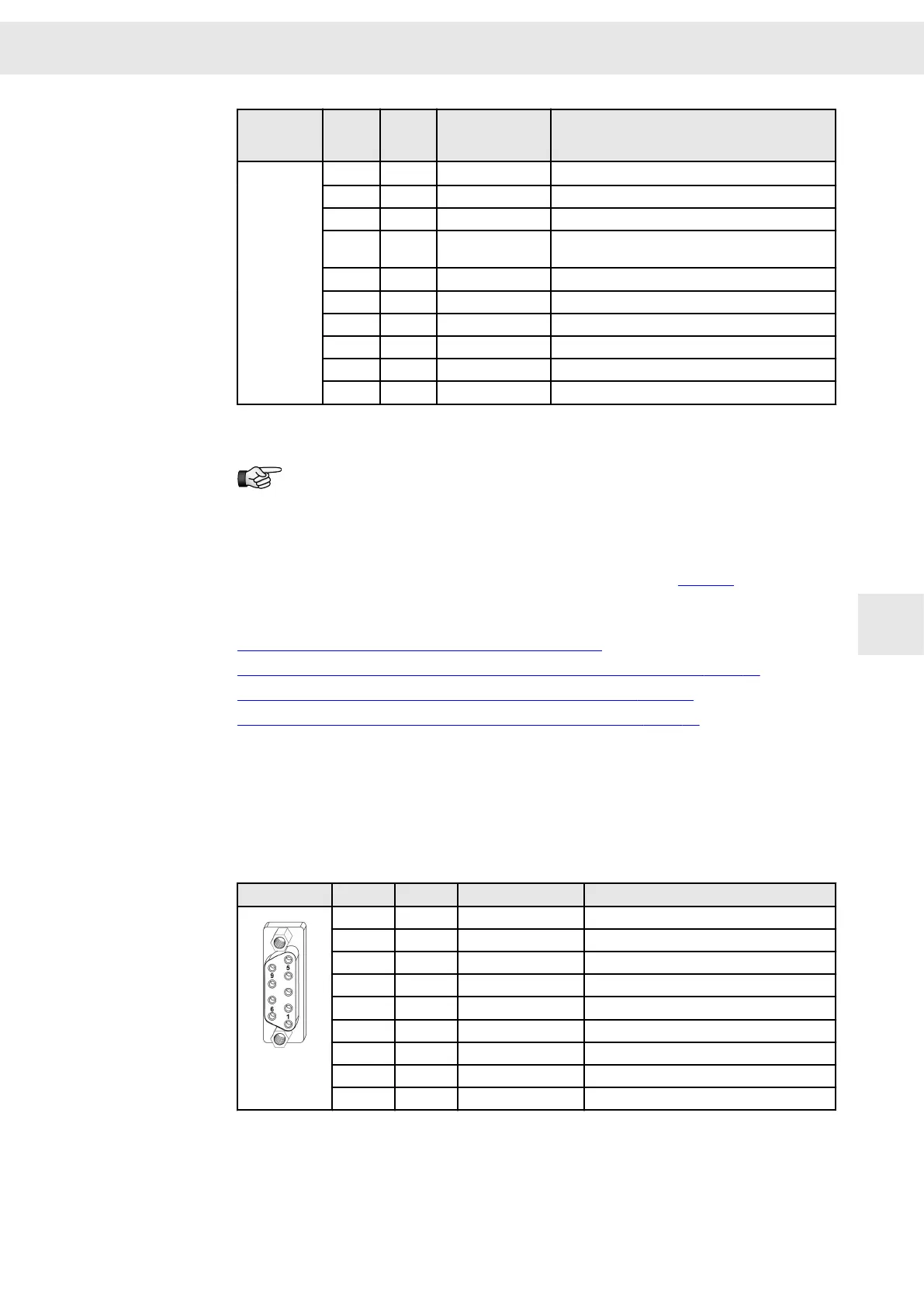
8.12 X15 – Encoder 0
Encoder 0 input, e.g. for length measuring systems
9-pole female submin D connector
X15
Pin I/O Name Meaning
1 I UA+ Track A+
2 I UA- Track A-
3 I UN+ Zero pulse+
4 I UN- Zero pulse-
5 I/O GND Ground
6 I UB+ Track B+
7 I UB- Track B-
8 O VCC_ENC 5.3 V supply voltage
9 I ERR Measuring system error
Stud bolt flange: max. tightening torque = 0.7 Nm
W
Connector Pin Assignment
Drive Amplifier SD2B / SD2B plus - Hardware Description 45
8