NOTICE
Voltage peaks during braking operation
During braking of high inertial masses and/or when using short braking times the
DC main voltage can increase significantly depending on the parameterized supply
voltage.
▶ supply voltage 24 V
DC
→ max. overvoltage 40 V
DC
▶ supply voltage 48 V
DC
→ max. overvoltage 70 V
DC
▶ supply voltage 80 V
DC
→ max. overvoltage 110 V
DC
The connected power supply unit must be designed for this voltage. If not, you
need to decouple the main voltage by means of a blocking diode to avoid damage
to the power supply unit (see connection example
page 48).
Related topics
Connection example: "X4/X6 – DC Power Supply Unit", page 48
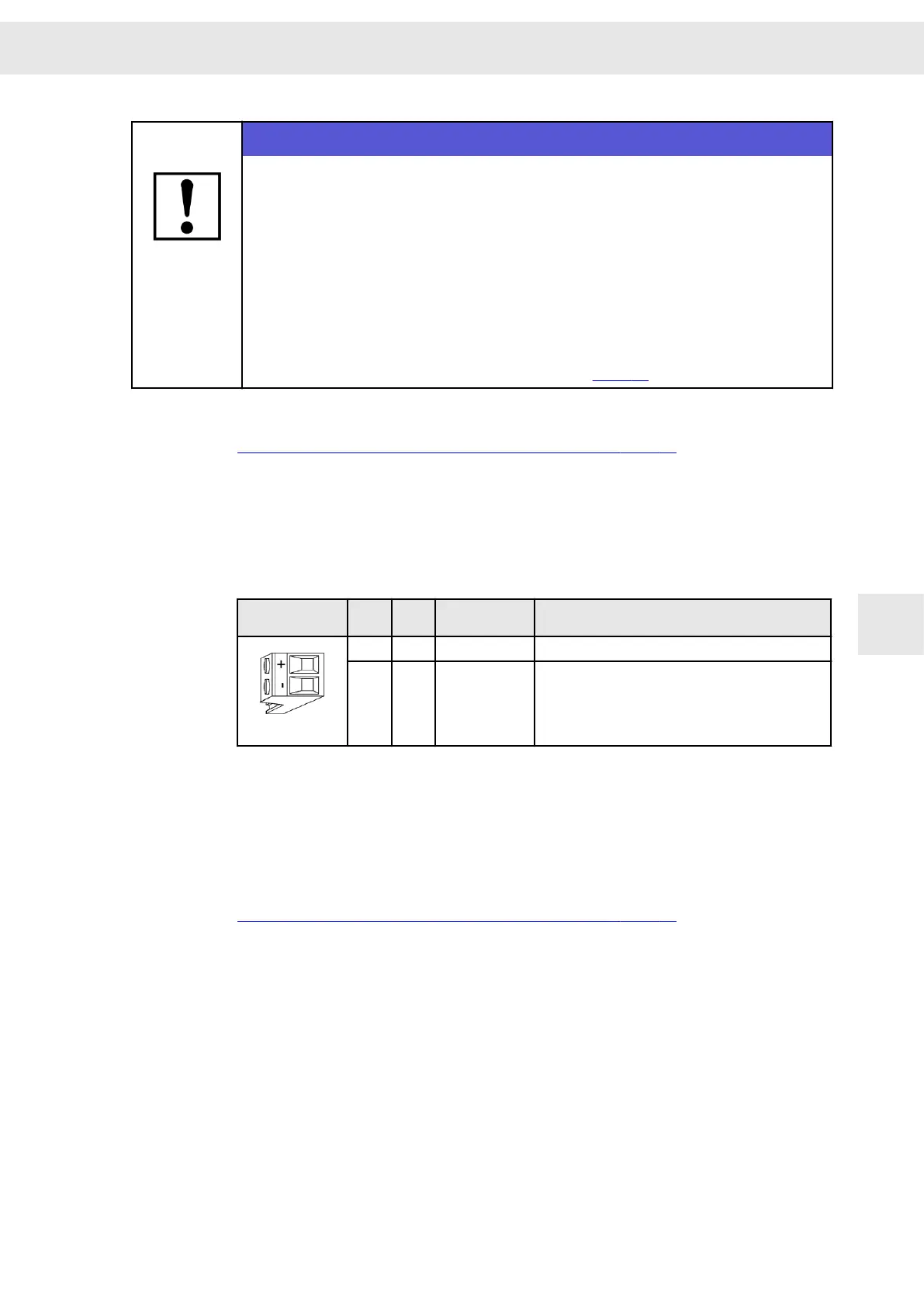
8.5 X6 – Logic Supply
2-pole Combicon connector, suitable for mating connector MSTB 2,5/ 2-ST-5,08
(Phoenix)
Mating connector
X6
Pin I/O Name Meaning
1 I +24V Logic supply +24 V
DC
(0.5 A)
2 I/O GND Ground
Always connect GND.
Voltage range: 24 V
DC
, voltage ripple max. 10 %
Specification of terminal connections
▶ Conductor cross-section solid/stranded: 0.2 to 2.5 mm²
▶ Tightening torque: 0.5 to 0.6 Nm
Related topics
Connection example: "X4/X6 – DC Power Supply Unit", page 48
8.6 X9 – Inputs/Outputs
The available functions of the inputs and outputs are different depending on the drive
function. You must set the desired function for each input/output in the software
drive‐
master2
.
W
Connector Pin Assignment
Drive Amplifier SD2B / SD2B plus - Hardware Description 41
8