DANGER
Danger due to electric shock
The restart lock does not galvanically separate the output stages from the motor.
Thus, the restart lock does not protect against electric shock.
The complete machine must always be galvanically separated from the mains by
use of the main switch(DIN EN 60204-1 5.3) for any interruptions of the operation,
maintenance, repair or cleaning work at the machine or system.
All mounting locations for safety devices of the control system as well as
components mounted outside have to correspond to an IP code IP54, if
mounted correctly.
13.1 Functional Description of the Restart Lock
The restart lock locks the respective drive of an installation. All further drive modules
(servo amplifiers / frequency converters) remains ready for operation.
A TÜV checked safety circuit accesses relevant control of the output stage transistors
of the drive to be locked by interrupting the voltage supply of the controls. Thus, no
control pulses can be passed on to the transistors of the output stages and the motor is
at a secure standstill.
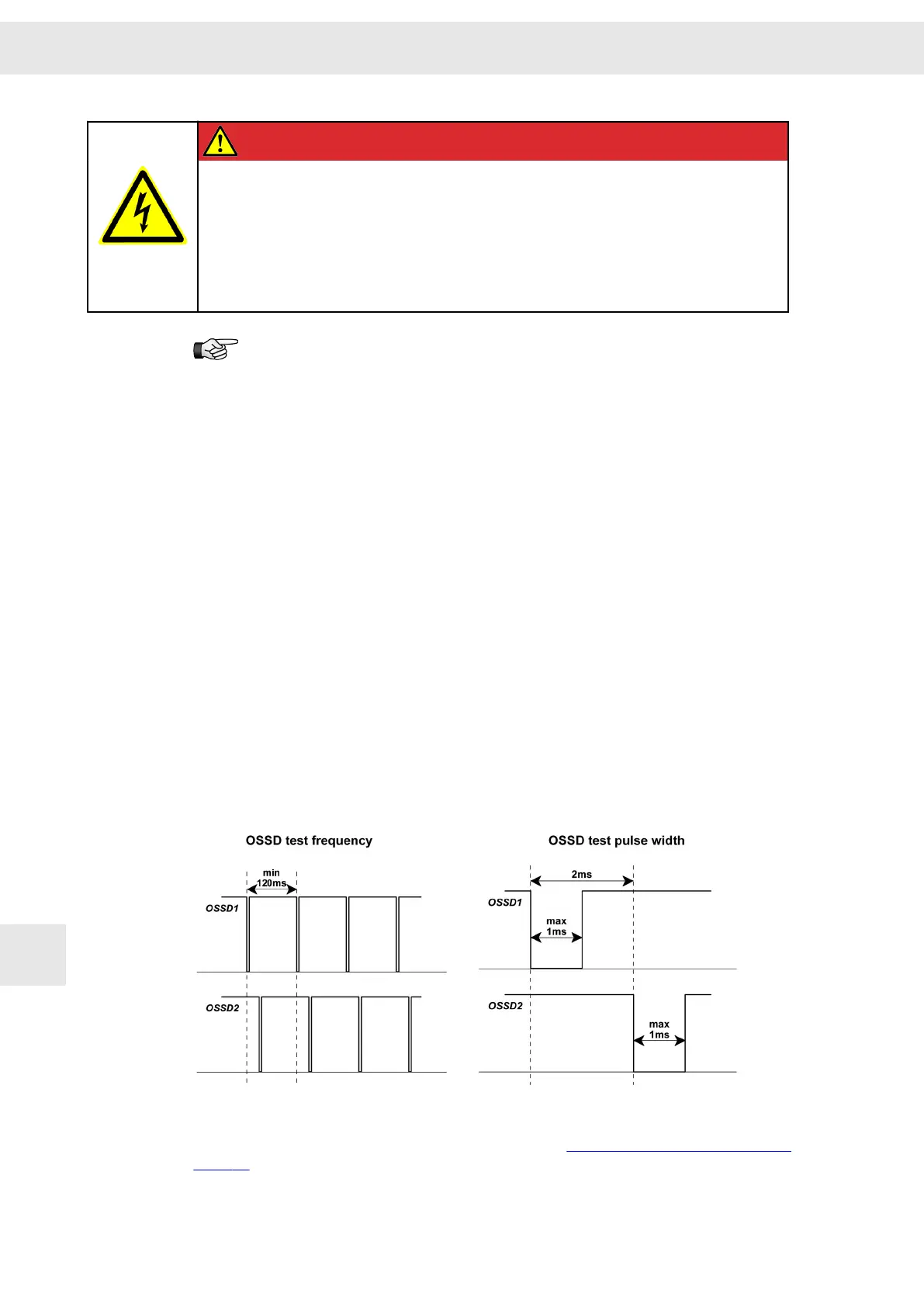
OSSD (Output Signal Switching Device)
Part of the contactless protective unit (German abbreviation = BWS) which is
connected with the machine control and which switches over into the OFF state, when
the sensor unit is triggered during the intended operation. (Source IEC 61496-1).
The OSSD signal is a pulsed signal, of which the phase position is shifted in relation to
the different channels. All error can be detected by checking the pulse pattern, short-
circuit for supply, cross-circuit or defect of the device. This ensures a very high safety
level (SIL 4).
The TÜV checked safety circuit is controlled by the OSSD1+2 signal or via one or
several emergency stop switch devices. See also section 13.2 "Wiring Example",
page 77
Safety Circuit / Restart Lock (STO)
W
76 Drive Amplifier SD2B / SD2B plus - Hardware Description
13