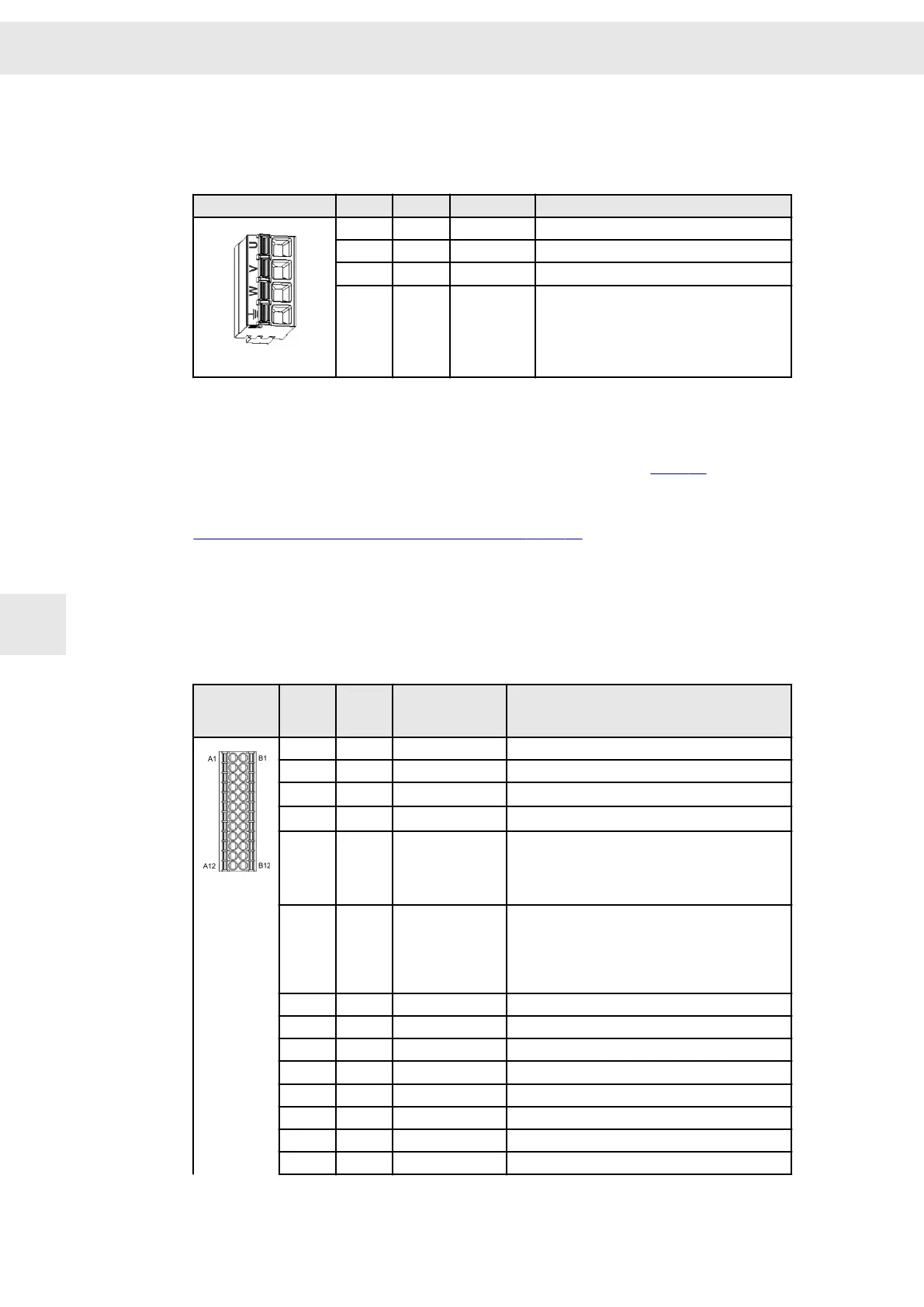
8.10 X13 – Motor Connection
4-pole Combicon connector, suitable for mating connector FKCN 2,5/ 4-ST-5,08
(Phoenix)
Mating connector X13
Pin I/O Name Meaning
1 O U Motor phase U
2 O V Motor phase V
3 O W Motor phase W
4 PE Protective conductor
Specification of terminal connections
▶ Conductor cross-section solid: 1 – 1.5 mm²
▶ Conductor cross-section stranded: 1 – 2.5 mm²
▶ Connection method: push-in spring connection (handling: see page 39)
Related topics
Connection example: "X2/X13 – Motor Phases", page 47
8.11 X14 – Inputs/Outputs / Safety Circuit (STO)
2 ×12-pole Mini-Combicon connector, suitable for mating connector DFMC 1.5/12-
ST-3.5 (Phoenix)
Mating
connector
X14
Pin
I/O Name Meaning
A1 I/O GND Ground
A2 I 24V IN Logic feed-in 24 V
A3 O
24V OUT
(1)
Logic supply 24 V
A4 O
24V OUT
(1)
Logic supply 24 V
A5 I SAFE B / OSSD2 Enable of the safety circuit
▶ Permanent load approx. 15 mA/24 V
▶ Startup peak current is negligible under
normal conditions.
A6
I SAFE A / OSSD1 Enable of the safety circuit
▶ Continous load at 24 V > 160 mA/24 V,
dependent on the device performance
▶ Startup peak current per device can exceed
8 A/24 V during the first 2 ms.
A7
I/O GND Ground
A8 O OUT4 Digital output
A9 O OUT3 Digital output
A10 O OUT2 Digital output
A11 O OUT1 Digital output
A12 O OUT0 Digital output
B1 I/O GND Ground
B2 I/O GND Ground
Connector Pin Assignment
W
44 Drive Amplifier SD2B / SD2B plus - Hardware Description
8