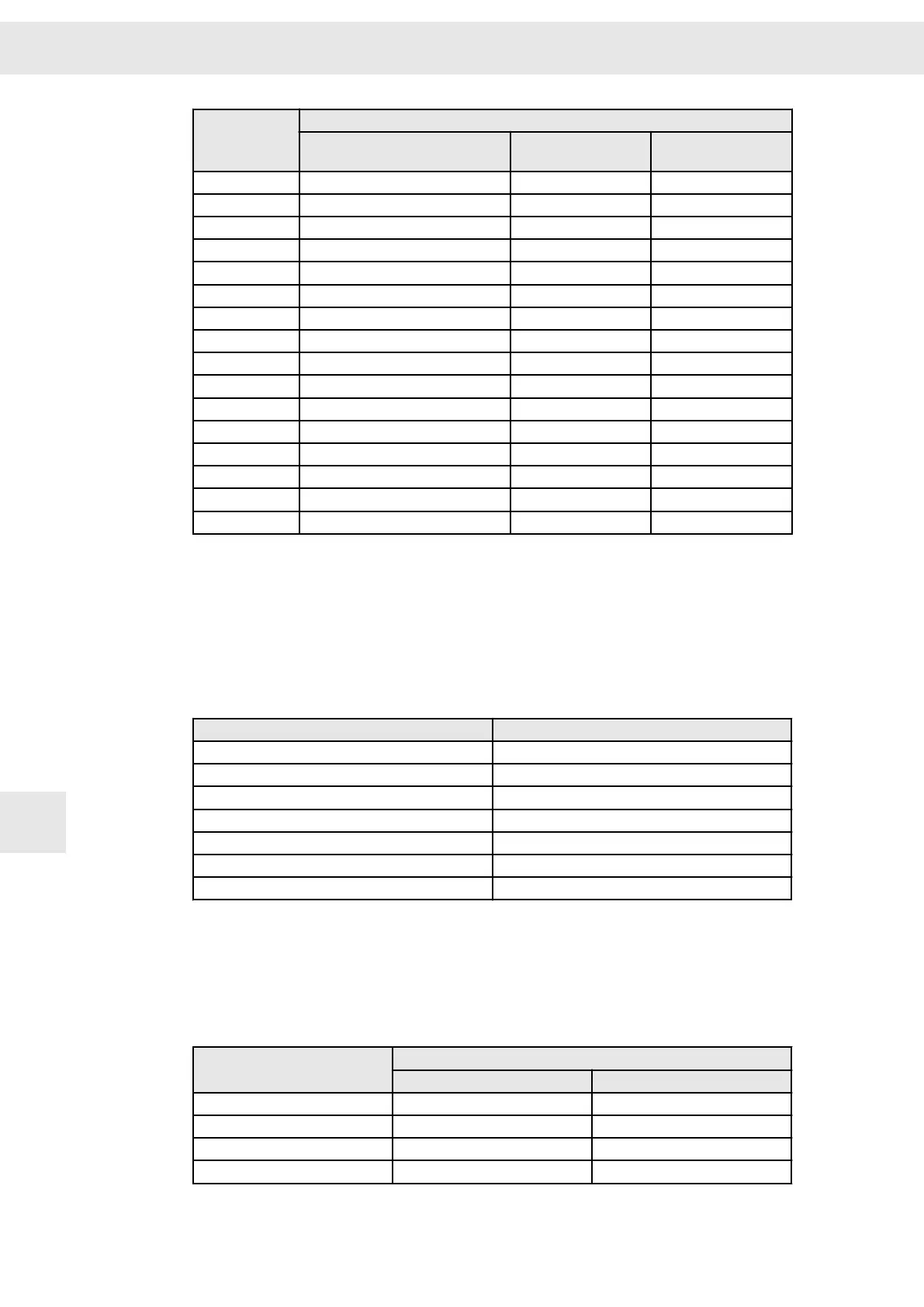
Conductor cross-
section A [mm²]
Admissible current I [A]
B2 wiring
(1)
E wiring (3 cable leads)
(2)
F wiring (3 cable leads)
(3)
6 29 37 –
10 40 52 –
16 53 70 –
25 67 88 96
35 83 110 119
50 100 133 145
70 130 171 188
95 150 207 230
120 175 240 268
150 – 277 309
185 – 317 356
240 – 374 422
300 – 433 488
400 – – 570
500 – – 652
630 – – 744
(1)
B2 wiring: wiring in installation tubes or closed installation channels.
(2)
E wiring: Free wiring of one cable with a min. distance of 0.3 × cable diameter to the wall.
(3)
F wiring: Free wiring of several cables with a min. distance of 1 × cable diameter to the wall.
Tab. 2: Current carrying capacity according to DIN VDE 0298-4
For detailed information refer to the standard IEC 60364-5-52 and the documents of
the cable manufacturer.
The following correction factors are provided for deviating ambient temperatures:
Ambient temperature T [°C]
Correction factor
30 1.15
35 1.08
40 1.00
45 0.91
50 0.82
55 0.71
60 0.58
Cross-sections of round conductors
The standard values of the cross-section of round copper conductors as well as the
approximate ratio of metric ISO and AWG/MCM values are shown in the following
table.
Standardized cross-sections of round conductors:
ISO cross-section [mm²]
AWG/MCM
Value Equivalent cross-section [mm²]
0.2 24 0.205
– 22 0.324
0.5 20 0.519
0.75 18 0.82
General Information Regarding the Wiring
W
68 Drive Amplifier SD2B / SD2B plus - Hardware Description
11