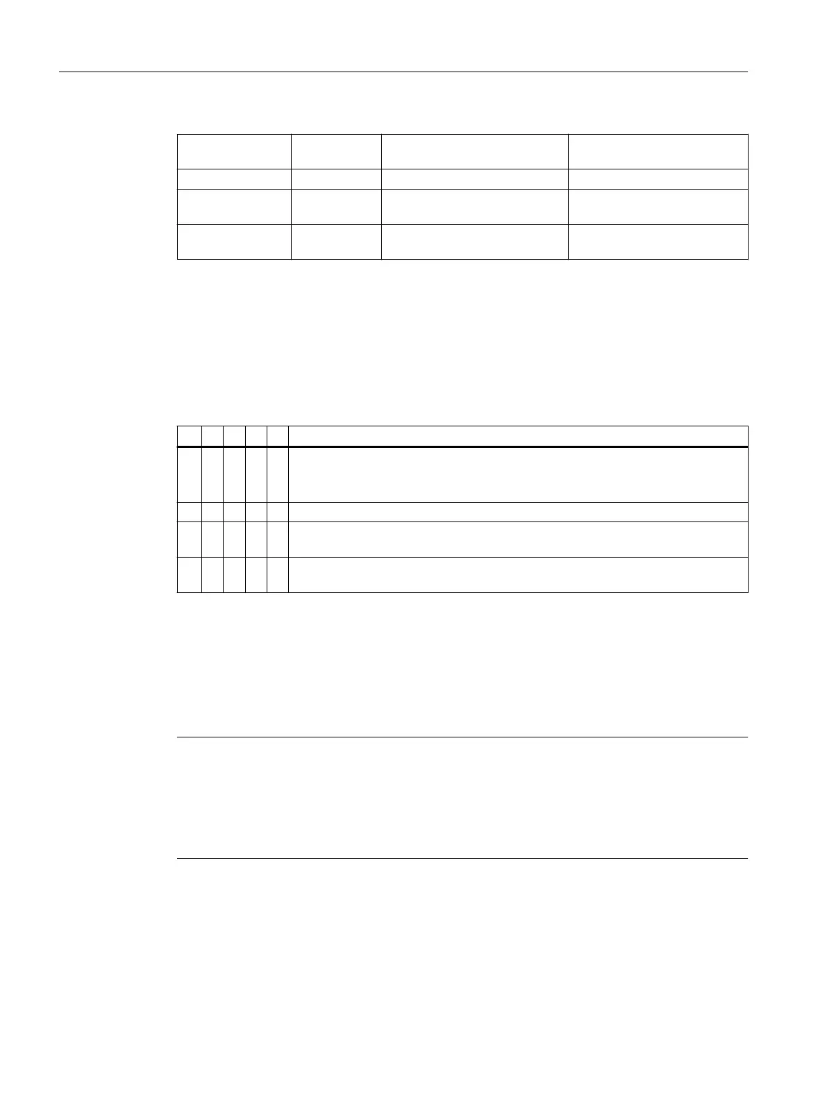
Direction of ro‐
tation
According to IEC According to NEMA
Line feeder cables - L1L2L3 L1L2L3
Terminal connec‐
tion
Clockwise ro‐
tation
UVW T1T2T3
Terminal connec‐
tion
Counter-clock‐
wise rotation
VUW T2T1T3
Direction of rotation of the motor when viewing the DE
6.2.2.3 Terminal marking
According to IEC / EN 60034‑8, the following basic denitions apply to the terminal markings for
3-phase machines:
Table 6-1 Terminal markings using the 1U1-1 as an example
1 U 1 - 1 Marking
x Code for split winding, where applicable. Special case for pole assignment for pole-
changing machines.
A lower index signies a lower speed.
x Phase designation U, V, W
x Index for winding start (1) or end (2) or if there is more than one connection per
winding
x Additional indices for cases in which it is obligatory to connect parallel power feed
cables to several terminals with otherwise identical markings
6.2.2.4 Cable entry
Assembly and laying of cables
Screw the screw-type connection into the housing or fasten with a nut.
Note
The screw-type connections must have been matched to the connecting cables used (diameter
armoring, braid, shield).
For the screw-type connections, comply or exceed the requirements relating to IP degree of
protection (water and dust) - as well as the temperature range in operation stamped on the
rating plate.
6.2.2.5 Versions
The terminal box can be turned 4x90 degrees on the terminal base of the machine's housing.
Electrical connection
6.2Connecting the machine
1LE1, 1FP1/3, 1PC1/3 shaft height 63 ... 315
66 Operating Instructions, 11/2023, A5E38483075A

 Loading...


