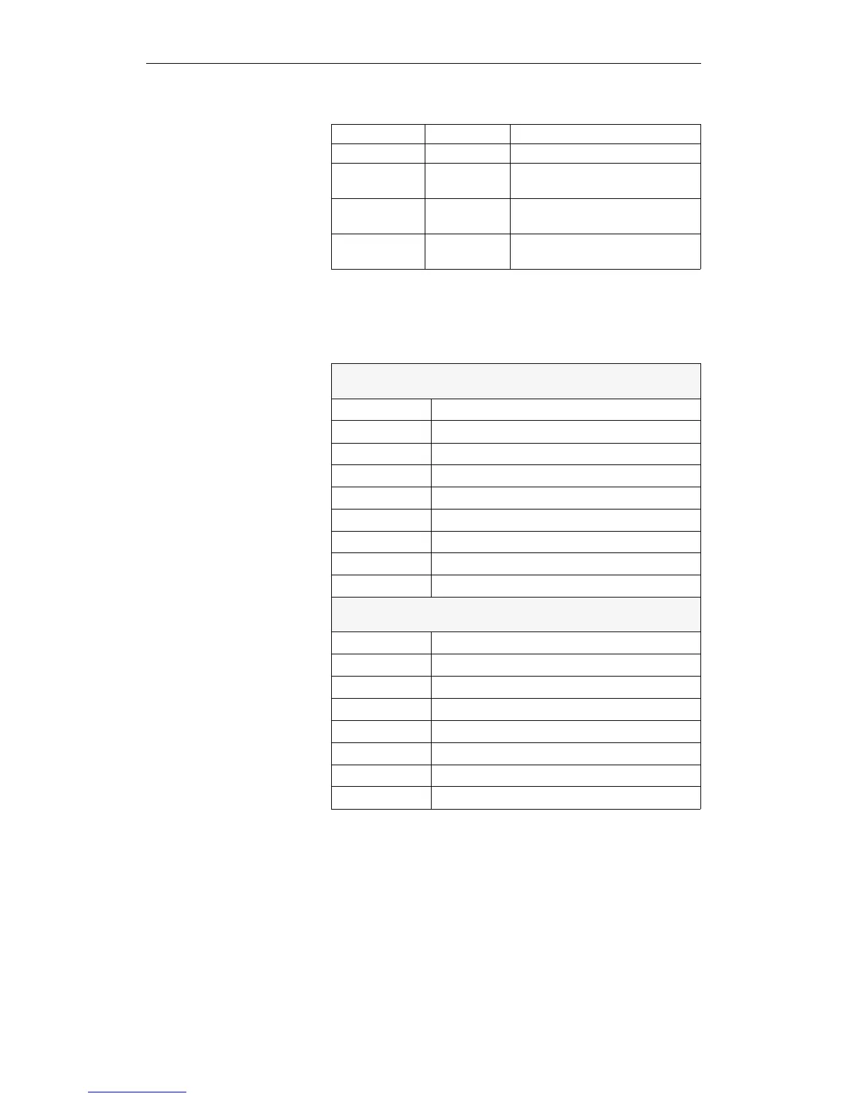
System data words
RS 16 to RS 47
Error areas
RS xx Address(es) Error area
RS 16 E F010 Output bytes 0 to 15
RS 17 to
RS 23
E F011 to
E F017
Output bytes 16 to 127
RS 24 to
RS 31
E F018 to
E F01F
Input bytes 0 to 127
RS 32 to
RS 47
E F020 to
E F02F
Interprocessor communication flag
bytes 0 to 255
RS 16
Address: E F010H
High byte
Bit no. Assignment
15 Output byte 0
14 Output byte 1
13 Output byte 2
12 Output byte 3
11 Output byte 4
10 Output byte 5
9 Output byte 6
8 Output byte 7
Low byte
7 Output byte 8
6 Output byte 9
5 Output byte 10
4 Output byte 11
3 Output byte 12
2 Output byte 13
1 Output byte 14
0 Output byte 15
If errors appear during update of the process image input/output tables
or interprocessor communication flags, the corresponding bits are set
to ’1’. – The system data words RS 17 to 47 are structured analogous
to RS 16.
Table 8-8 Bits of RS 16 (error area output bytes 0 to 15)
Bit Assignment of the System Data Words
CPU 948 Programming Guide
C79000-G8576-C848-04
8 - 23