3.5.2
Programming Examples in
the STL, LAD and CSF
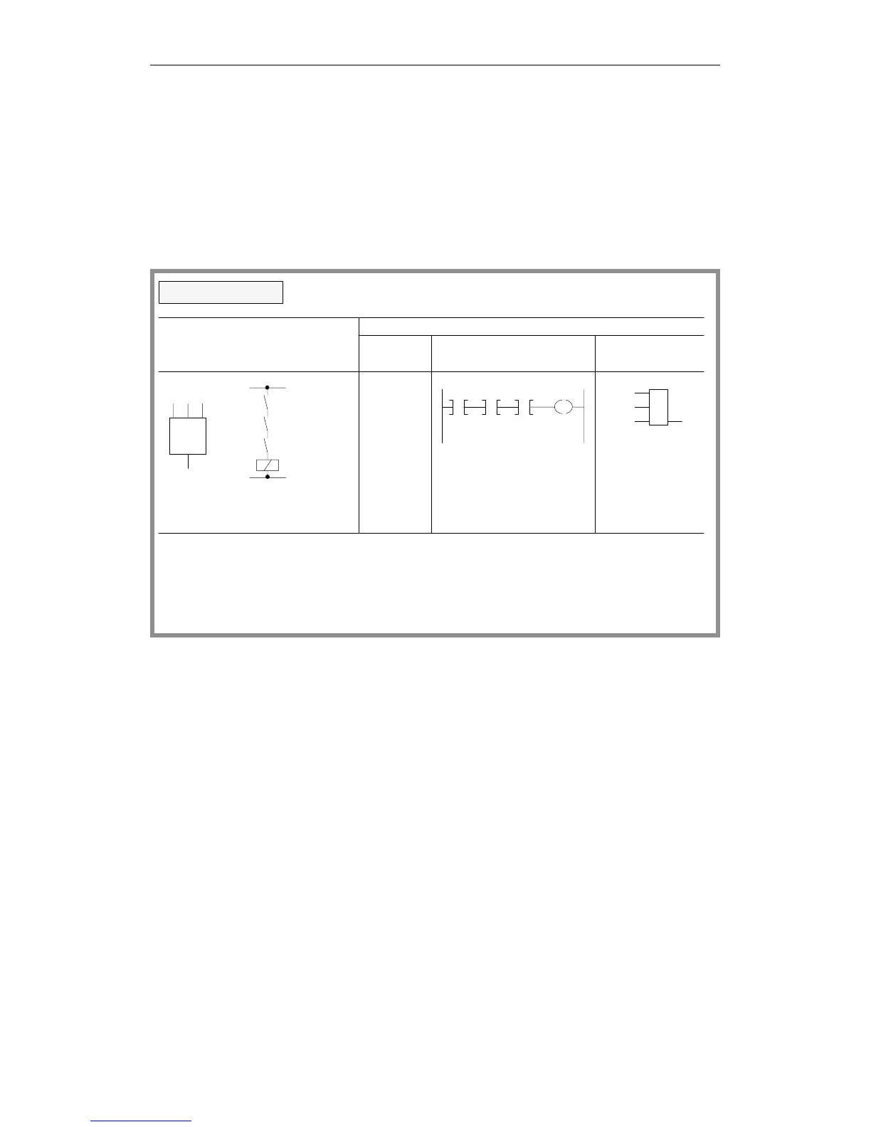
Methods of Representation
Logic operations
I 1.7
I 1.3
I 1.1
Q 3.5
Logical/circuit diagram
STEP 5 representation
Ladder Control system
A
I 1.1
A
A
I 1.3
I 1.7
= Q3.5
I 1.1 I 1.3 I 1.7 Q 3.5
I 1.1 1.3 1.7
Q 3.5
&
Output Q 3.5 is "1" when all inputs are "1" simultaneously
I 1.1
I 1.3
I 1.7 Q 3.5
&
Statement
list
AND operation
diagram flowchart
Output Q 3.5 is "0" if any of the inputs has signal state "0"
The number of scans and the sequence of the logic
statements are optional
Programming Examples in the STL, LAD and CSF Methods of Representation
CPU 948 Programming Guide
3 - 34 C79000-G8576-C848-04